

Air cycle machine for an aircraft environmental control system
- Summary
- Abstract
- Description
- Claims
- Application Information
AI Technical Summary
Benefits of technology
Problems solved by technology
Method used
Image

Examples
Embodiment Construction
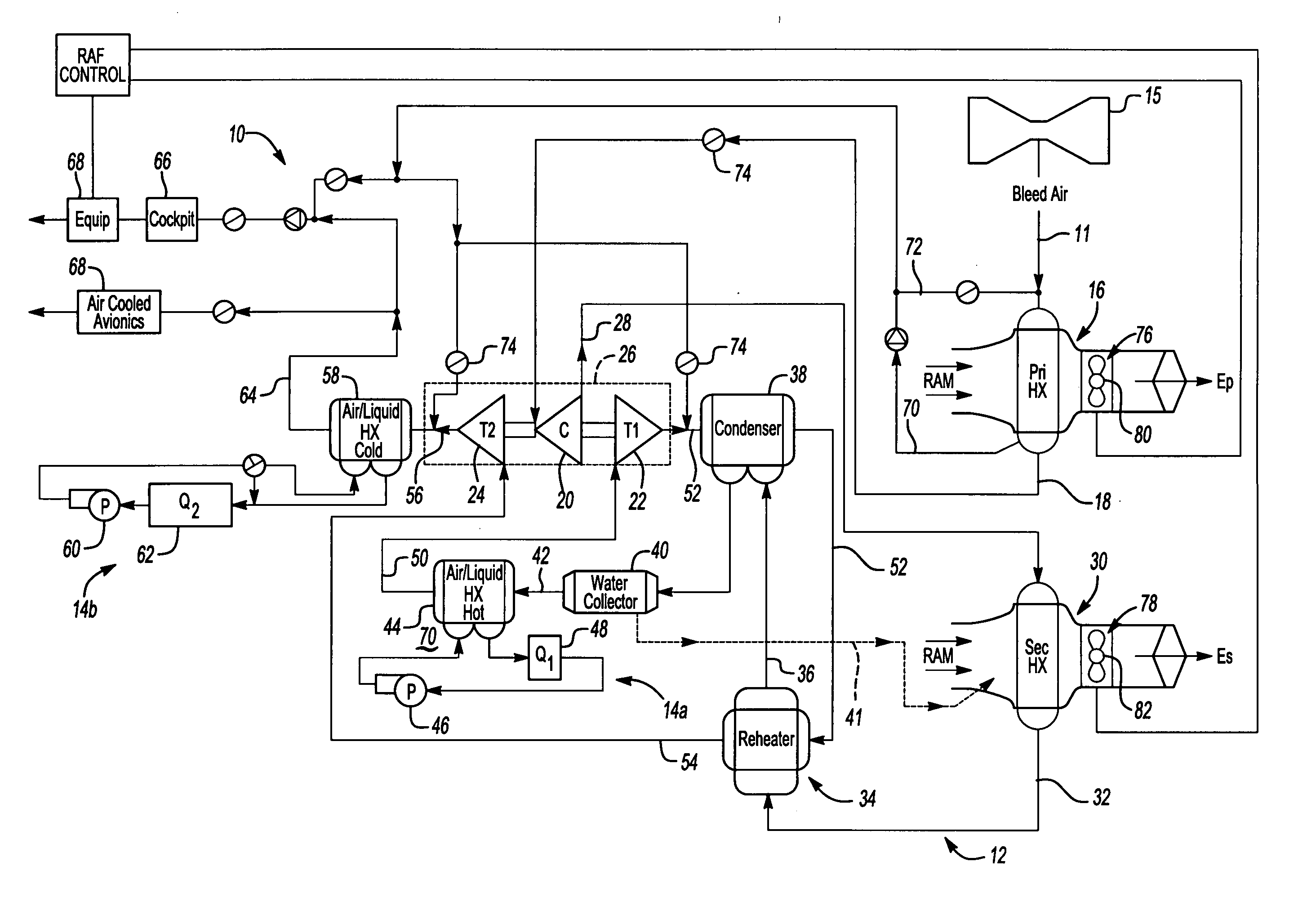
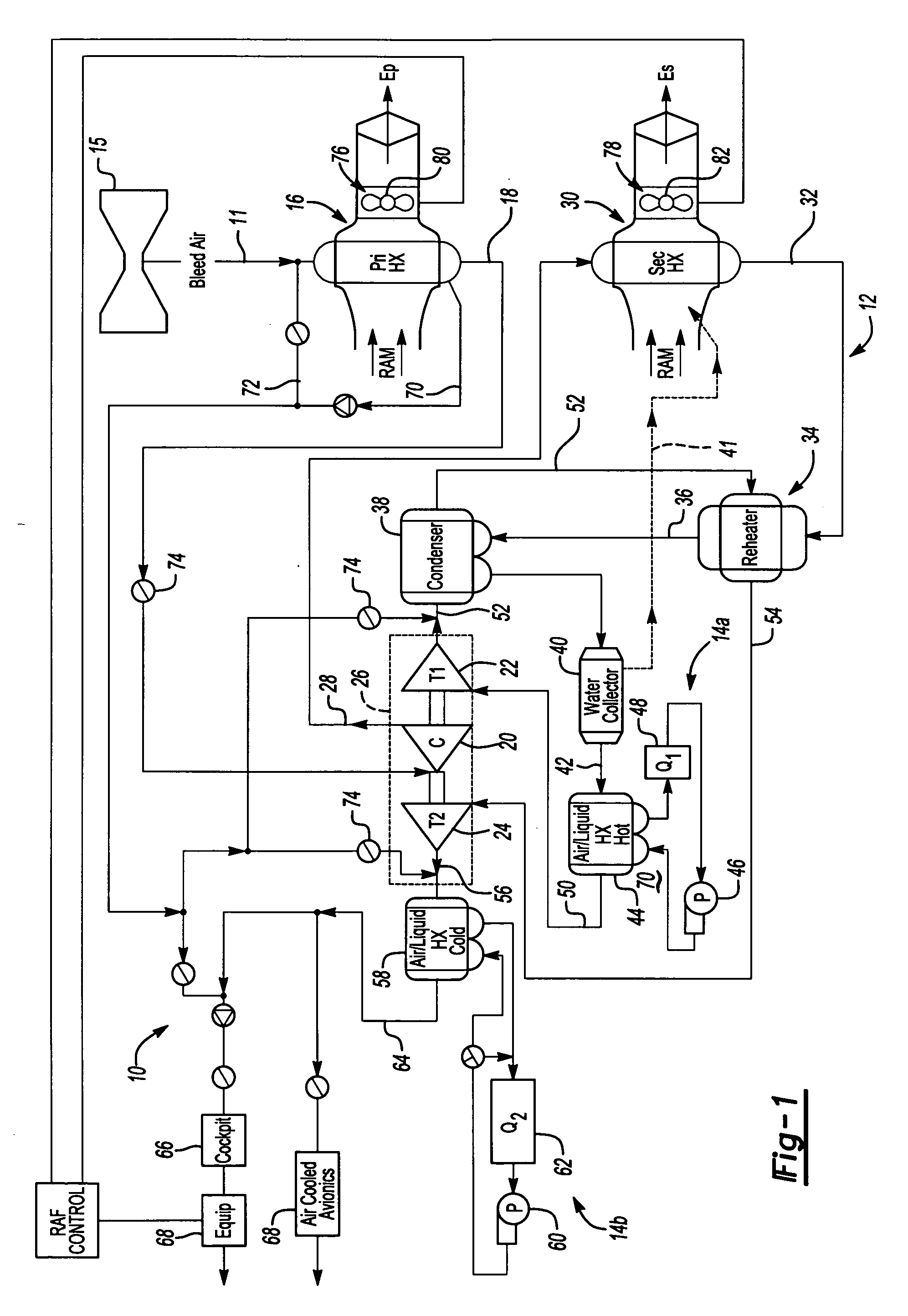
[0013]FIG. 1 illustrates a general schematic view of a liquid-to-air cycle system or environmental control system (ECS) 10. The ECS 10 includes an air cycle subsystem 12 that is in a heat exchange relationship with a liquid cycle subsystem 14a, 14b. It should be understood that although two separate liquid subsystems are disclosed in the illustrative embodiment, a single substantially continuous subsystem will also benefit from the present invention.
[0014] Bleed air 11 is preferably received from a gas turbine engine (illustrated schematically at 15). The bleed air 11 is sent through a primary heat exchanger 16 such that the bleed air 11 is in heat exchange relationship with RAM or ambient air. The primary heat exchanger 16 is preferably an air-to-air exchanger. After the bleed air 11 is cooled in the primary heat exchanger 16, the resulting cooler air is communicated through a passage 18 which communicates with a compressor 20 where the air is compressed to a high pressure. The co...
PUM
 Abstract
Description
Claims
Application Information