Workpiece ejecting device for a machine tool

a technology of ejecting device and machine tool, which is applied in the direction of chucks, mechanical equipment, manufacturing tools, etc., can solve the problems of bending deformation of the ejecting rod, malfunction of the ejecting operation, etc., and achieve the effect of preventing vibration, noise and frictional heat, and ejecting smoothly

Active Publication Date: 2006-03-23
DN SOLUTIONS CO LTD
View PDF9 Cites 4 Cited by
  • Summary
  • Abstract
  • Description
  • Claims
  • Application Information

AI Technical Summary

Benefits of technology

[0011] Therefore, the present invention has been made in view of the above problems occurring in the prior art, and it is an object of the present invention to provide an workpiece ejecting device for a machine tool, in which the ejecting ba

Problems solved by technology

In addition, when the spindle rotates at high velocity above 5,000 rpm, the ejecting rod 20 produces vibration, noise and heat to thereby cause bending deformation of

Method used


Image

  • Workpiece ejecting device for a machine tool
  • Workpiece ejecting device for a machine tool
  • Workpiece ejecting device for a machine tool

Examples


first embodiment

[0027] In the first embodiment of the present invention, the rod of the ejecting cylinder is configured in such a fashion that its length extends to a position adjacent to a chuck so that it can perform ejection function, and it is configured to be supported by a front bearing unit so that it cannot rotate together with a spindle or a drawing tube. Also, cutting oil can be supplied via a fluid passing opening formed passing through the center of the rod in the ejecting cylinder in the longitudinal direction.

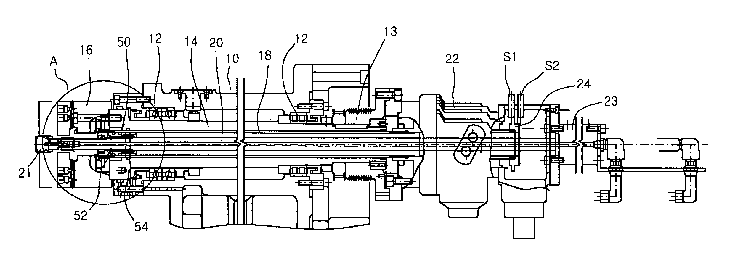
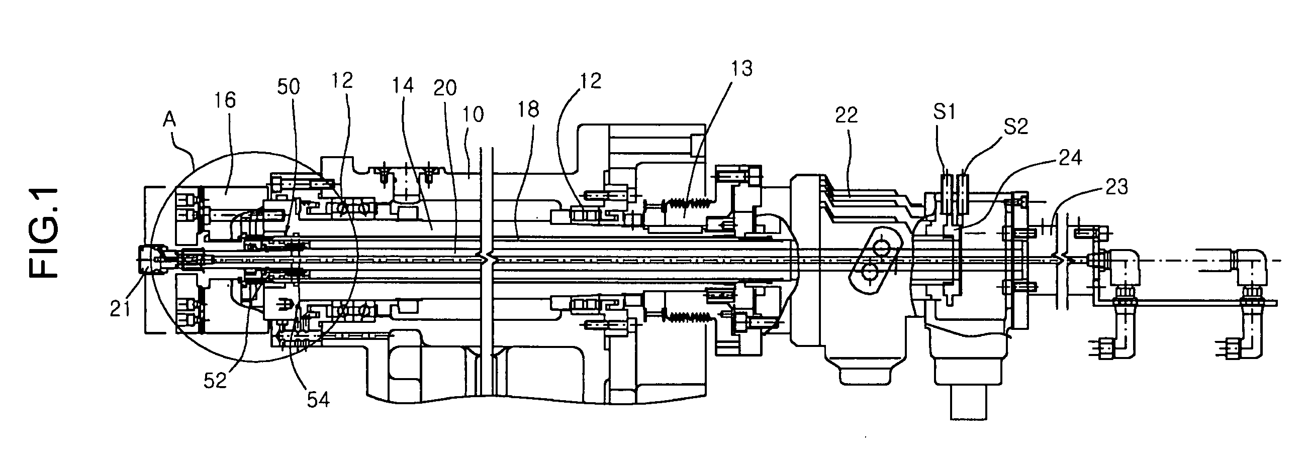
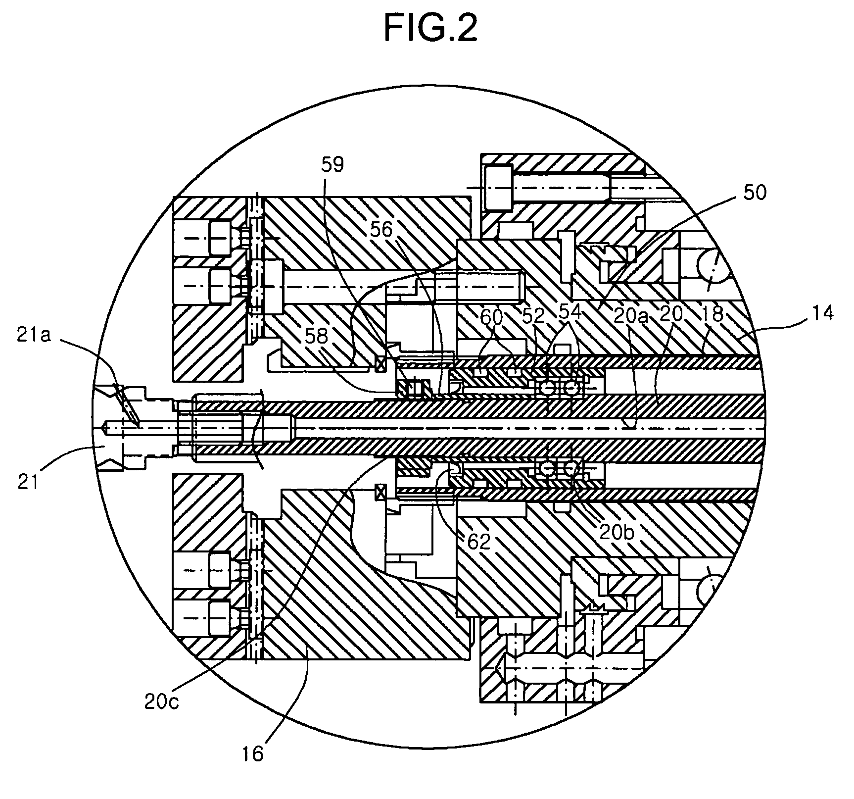
[0028]FIG. 1 is an assembly sectional view showing structure of the workpiece ejecting device of an NC lathe according to the first embodiment of the present invention, and FIG. 2 is an enlarged view of portion “A” in FIG. 1.

[0029] In the first embodiment of the present invention, as shown in FIG. 1 and FIG. 2, a spindle 14 is installed to a head stock 10, and is rotatably supported by a bearing 12. The spindle 14 is provided with a spindle pully 13 configured to be rotated by ...

second embodiment

[0052] As shown in FIG. 3, the second embodiment of the present invention modifies the supporting structure of the rear end of the ejecting rod, which is used for ejecting the workpiece. FIG. 4 shows a side view of FIG. 3.

[0053] In the second embodiment, the ejecting rod is so configured that it cannot rotate integrally with the drawing tube 18. In this regard, the front end of the ejecting rod is adapted to be supported by the front bearing unit 50 as was in the first embodiment. Also, it is characterized in that the rear end of the ejecting rod is supported by means of the rear end dual bearing unit 200.

[0054] Also, in the second embodiment of the present invention, the ejecting cylinder 23 is arranged in parallel with the ejecting rod 20, and the piston rod 23a of the ejecting cylinder 23 is connected to the rear end of the ejecting rod 20 via a connection member 225.

[0055] Hereinafter, the operation and structure of the rear end dual bearing unit 200 supporting the rear end o...


PUM

PropertyMeasurementUnit
Velocityaaaaaaaaaa

Abstract

Disclosed herein is a workpiece ejecting device for a machine tool, in which the ejecting bar cannot be rotatably driven at the time of high velocity rotation of the spindle to thereby prevent occurrence of vibration, noise and frictional heat owing to the movement of the spindle, so that the machined workpiece can be ejected smoothly. According to the first embodiment of the present invention, there is provided a workpiece ejecting device for a machine tool for ejecting a workpiece clamped to a chuck installed at a spindle by means of a drawing tube connected to a chucking cylinder, the workpiece ejecting device comprising: a front bearing unit installed at an inner peripheral surface of a front end portion of the drawing tube to support the rotation of the drawing tube; and an ejecting cylinder located behind the chucking cylinder and installed directly on an axial line identical with that of the front bearing unit, and having an ejecting rod, wherein the ejecting rod is provided at a center axis thereof with at least one fluid passing opening through which fluid for removing alien materials is supplied, and a front end of the ejecting rod is installed to be supported by the front bearing unit.

Description

BACKGROUND OF THE INVENTION [0001] 1. Field of the Invention [0002] The invention relates to a device for automatically ejecting a workpiece chucked to a spindle in a machine tool, in particular, to such a workpiece ejecting device for the machine tool, which can smoothly eject the workpiece by means of separate ejecting operation without any affection from the rotation of the spindle. [0003] 2. Background of the Related Art [0004] In general, a spindle of the machine tool (for example, an NC lathe and the like) is provided at opposite side of a main spindle to perform cutting work of a workpiece, and the cutting worked workpiece is ejected automatically from a chuck by means of ejection operation of the ejecting device. [0005] The conventional ejecting device for the spindle for automatically ejecting the workpiece is shown in FIG. 5 showing an assembling section of the conventional spindle assembly. As shown in the drawing, a chuck 16 is mounted at the spindle 14 to clamp the work...

Claims


Application Information

Patent Timeline
IPC IPC(8): B23B13/00
CPCB23B31/003B23Q7/006Y10T82/2514Y10T408/51Y10T82/2552Y10T82/26Y10T279/3487
Inventor JOO, TAE HWANKWON, KYEONG SIK
Owner DN SOLUTIONS CO LTD
Why Eureka
Try Eureka