Diffuser gravity support

a gravity support and diffuser technology, applied in the direction of coatings, chemical vapor deposition coatings, plasma techniques, etc., can solve the problems of affecting the appearance of the diffuser, the edge support scheme does not provide any support for the center portion, and the diffuser is difficult to adjust the profile, so as to avoid the distortion of the diffuser. , the effect of facilitating the adjustment of the diffuser

Active Publication Date: 2006-03-23
APPLIED MATERIALS INC
View PDF98 Cites 226 Cited by
  • Summary
  • Abstract
  • Description
  • Claims
  • Application Information

AI Technical Summary

Benefits of technology

[0009] The invention generally relates to a method and apparatus for supporting a gas distribution plate, or diffuser, in a plasma chamber. In one embodiment, the diffuser is suspended by at least one interior or centrally located support member coupled to the gas distribution plate and a wall of the chamber. The invention is advantageous to avoid distortion of the diffuser in response to gravitational, and thermal or pressure induced forces acting on the diffuser while enduring the high temperatures created during plasma-enhanced chemical vapor deposition. The at least one support member is coupled between the diffuser and backing plate within the chamber and is capable of adjusting the planar orientation of the diffuser. The at least one support member is configured to adjust the diffuser profile pre or post evacuation of the chamber. In another embodiment, the at least one support member facilitates adjustment of the diffuser profile by adjustment of a plurality of screws coupled to the at least one support member. The gravitational support may be attached to the diffuser without compromising flow of the gas or gasses through the diffuser.

Problems solved by technology

If the diffuser is somehow warped during deposition, the process may not produce uniform deposition, which may result in an unusable flat panel display.
The larger diffuser size has presented new challenges to design a diffuser that will resist sag when exposed to high temperatures during deposition.
However, this edge support scheme does not provide any support for the center portion, which can tend to sag or creep over time, due to the forces of gravity aggravated by high processing temperatures during the CVD or PECVD processes.

Method used


Image

  • Diffuser gravity support
  • Diffuser gravity support
  • Diffuser gravity support

Examples


Embodiment Construction

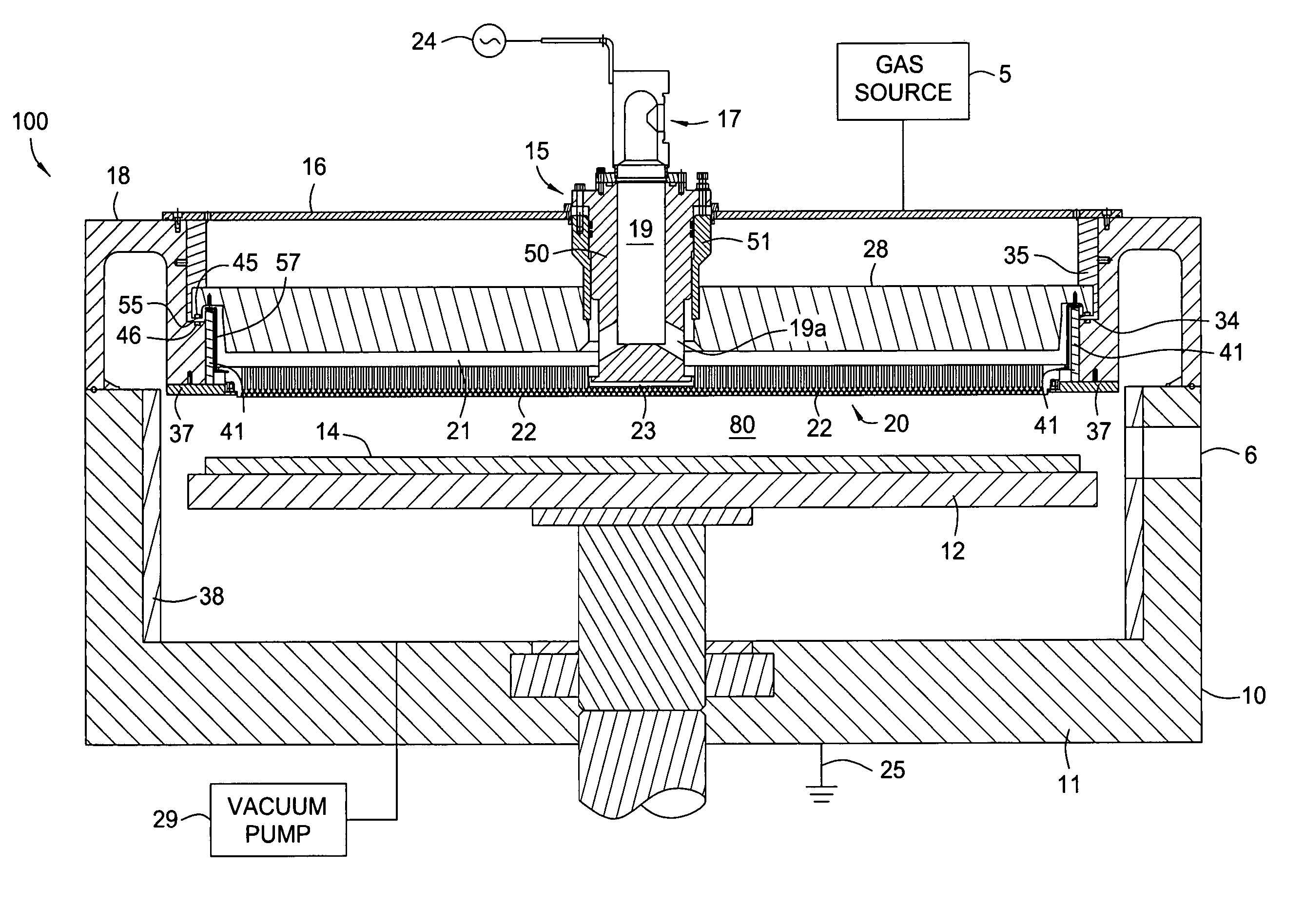
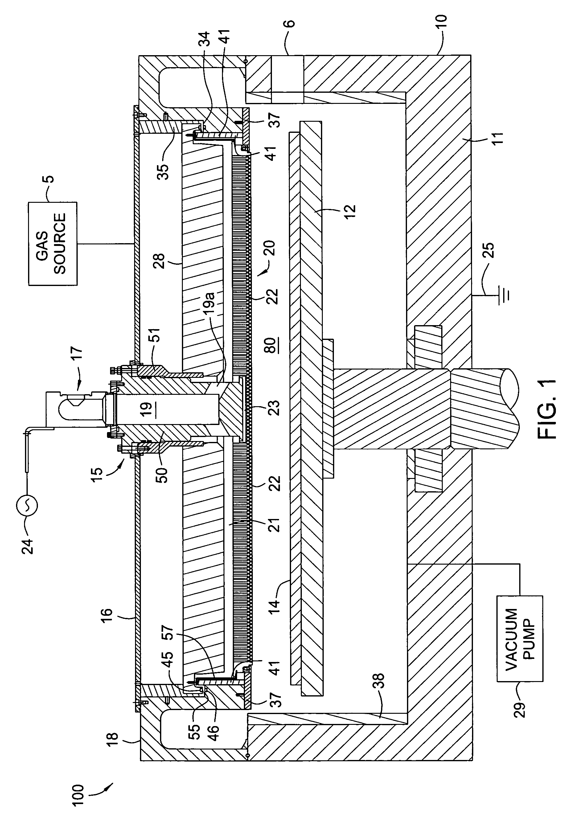
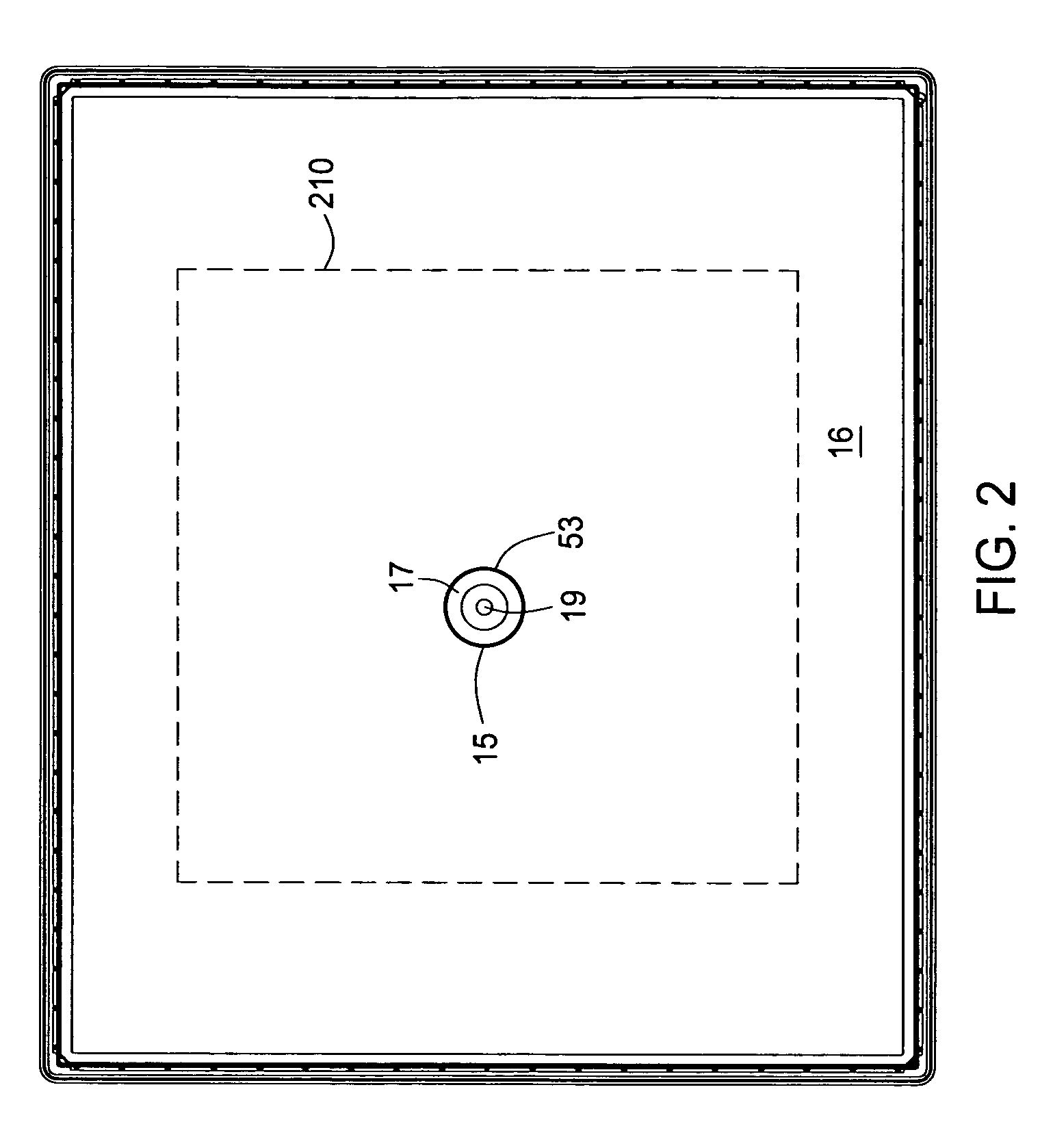
[0044] Embodiments of the present invention generally provide an apparatus and method for supporting a gas distribution plate in a processing chamber. In one embodiment, at least one support member is configured to support the gas distribution plate and facilitates resistance to center sag or bowing caused by gravitational forces and high processing temperatures, thereby maintaining a desired horizontal profile in the gas distribution plate. The desired horizontal profile may be at least one of a level horizontal profile, a convex horizontal profile, or a concave horizontal profile. The horizontal profile or orientation of a gas distribution plate or diffuser as used herein refers to a cross section of the gas distribution plate as shown in the applicable Figures. In all embodiments, the gas distribution plate has at least one support member coupled to a center area of the gas distribution plate, wherein, by adjusting the at least one support member, the center area is adjustable to...


PUM

PropertyMeasurementUnit
temperatureaaaaaaaaaa
temperaturesaaaaaaaaaa
sizeaaaaaaaaaa

Abstract

An apparatus and method for supporting a substantial center portion of a gas distribution plate is disclosed. At least one support member is capable of engaging and disengaging the diffuser with a mating connection without prohibiting flow of a gas or gasses through the diffuser and is designed to provide vertical suspension to a diffuser that is supported at its perimeter, or capable of supporting the diffuser without a perimeter support. In one aspect, the at least one support member is a portion of a gas delivery conduit and in another embodiment is a plurality of support members separated from the gas delivery conduit. The at least one support member is capable of translating vertical lift, or vertical compression to a center area of the diffuser. A method and apparatus for controlling gas flow from the gas delivery conduit to the gas distribution plate is also disclosed.

Description

CROSS-REFERENCE TO RELATED APPLICATIONS [0001] This application claims priority to U.S. Provisional Application No. 60 / 611,512, filed Sep. 20, 2004, and U.S. Provisional Application No. 60 / 653,617, filed Feb. 16, 2005, both applications incorporated by reference herein.BACKGROUND OF THE INVENTION [0002] 1. Field of the Invention [0003] Embodiments of the present invention generally relate to supplying a gas or gasses to a plasma chamber. More specifically, the invention relates to supporting a gas distribution plate within the chamber. [0004] 2. Description of the Related Art [0005] Flat panel displays employ an active matrix of electronic devices, such as insulators, conductors, and thin film transistors (TFT's) to produce flat screens used in a variety of devices such as television monitors, personal digital assistants (PDA's), and computer screens. Generally, these flat panel displays are made of two thin panels of glass, a polymeric material, or other suitable substrate material...

Claims


Application Information

Patent Timeline
Patent Type & Authority Applications(United States)
IPC IPC(8): C23C16/00
CPCH01J37/3244C23C16/45565
Inventor KELLER, ERNSTWHITE, JOHN M.TINER, ROBIN L.KUCERA, JIRICHOI, SOO YOUNGPARK, BEOM SOOSTARR, MICHAEL
Owner APPLIED MATERIALS INC
Why Eureka
Try Eureka