Pneumatic tire

a technology of pneumatic tires and lateral slippage, which is applied in the direction of vehicle components, transportation and packaging, non-skid devices, etc., can solve the problems of remarkable performance deterioration, lateral slippage at the corner becomes large, performance deterioration, etc., and achieves stable steering stability and wear resistance. a large improvement

Inactive Publication Date: 2006-03-23
BRIDGESTONE CORP
View PDF11 Cites 11 Cited by
  • Summary
  • Abstract
  • Description
  • Claims
  • Application Information

AI Technical Summary

Benefits of technology

[0010] It is, therefore, an object of the invention to provide a pneumatic tire suitable for competitive sports, particularly a pneumatic tire for a racing cart having an excellent steering stability under wet conditions by improving the tread pattern to stably ensure the gripping performance compatible with the wide range of water volume conditions.
[0011] The inventors have made various studies for solving the above problems and found that the tread pattern is rendered into the construction mentioned later, whereby the lowering of the pattern rigidity or wear resistance in the shoulder portion, which results in the lowering of the lateral force even under a small water volume condition, can be prevented without damaging the drainage property and hence the stable running performances can be developed under conditions ranging from a large water volume to a small water volume, and as a result, the invention has been accomplished.
[0014] According to the invention, a tread pattern based on the bell-shaped wide-width main grooves is adopted for substantially reducing the circumferential main grooves, and the circumferential main groove is removed from the shoulder portion violently causing the wearing, whereby the wear resistance can be largely improved while sufficiently ensuring the total groove area, and hence the improvements of the resistance to hydroplaning under a large water volume condition and the wear resistance under a small water volume condition and it is possible to realize a pneumatic tire capable of stably developing the steering stability irrespectively of the increase or decrease of the water volume.

Problems solved by technology

In such a tread pattern, however, there is a problem that as the water volume is decreased by the change of weather condition, the lateral slippage at the corner becomes large due to the lacking of rigidity in the blocks of the pattern and the performance deterioration is caused.
As a result, as the water volume might become less, there is caused a remarkable performance deterioration that the lateral slippage becomes larger due to the phenomenon that the block rigidity is lacking or the lowering of lateral force produced in the cornering accompanied with the progress of wearing at shoulder blocks.
On the other hand, as a largish block pattern is adopted by placing importance on the performance when the water volume is small, the total groove area in the limited ground contact area is decreased, and hence the hydroplaning phenomenon is liable to be easily caused under a condition that the water volume is large to finally bring about the deterioration of the steering stability.
In the conventional wet tires for the racing cart, since the block pattern comprising four main circumferential grooves as a front tire or five main circumferential grooves as a rear tire is commonly used as previously mentioned, there is a problem that as the water volume becomes less, the wearing of the blocks located at the inside of the mounting becomes fast to bring about the lowering of the lateral force produced and the lowering of the braking force.
As a counter-measure, it is mentioned to make the block large, which decreases the total groove area in the limited ground contact area of the tire for the racing cart being light in the load as long as it is positioned on an extension of the conventional block pattern based on the main circumferential grooves, so that it has not yet led to prevent the problem of easily causing the hydroplaning phenomenon or the occurrence of uneven wear along the main circumferential groove.

Method used


Image

  • Pneumatic tire
  • Pneumatic tire
  • Pneumatic tire

Examples


Embodiment Construction

[0019] The invention will be described below with reference to the preferred embodiments shown in the accompanying drawings.

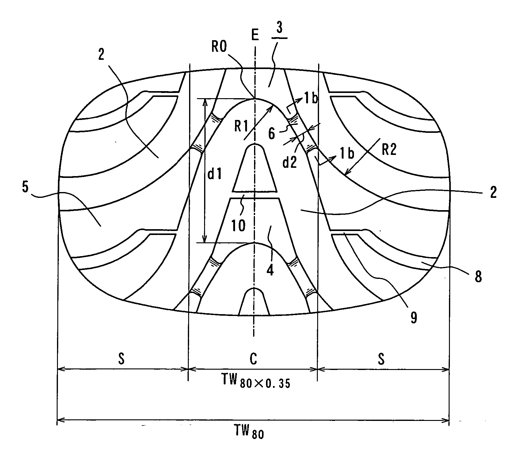
[0020] In FIG. 1a is shown a tread pattern of a pneumatic tire according to the first aspect of the invention. This tire has a central region C corresponding to TW80×35% and both shoulder regions S when TW80 is a ground contact width of a tread in the tire mounted on a rim of 4.5-5 inches under an internal pressure of 100 kPa and a load of 784 N.

[0021] In the first aspect of the invention, it is required that a wide-width main groove continuously extending in the circumferential direction of the tire is not arranged in the shoulder region S for reducing the wearing of the shoulder portion under a small water volume condition, and also a wide-width main groove continuously extending in the circumferential direction is not arranged in the central region, from which it is anticipated to lower the drainage property under a large water volume condition. In the inv...


PUM


Abstract

A pneumatic tire suitable for competitive sports has a specified tread pattern comprising a central region and both shoulder regions, in which a plurality of bell-shaped wide-width main grooves each extended substantially bell-shapedly into both sides approximately centering on an equator of the tire are disposed in the tread at a given interval in the circumferential direction of the tire wherein the bell-shaped wide-width main groove has specified inclination angles in the central region and the shoulder region and specified groove width and groove depth, and a width of a connecting land portion at a position coming the bells-shaped wide-width main grooves closest to each other is not less than 1.5 mm, and the tire has a given negative ratio at the central region.

Description

BACKGROUND OF THE INVENTION [0001] 1. Field of the Invention [0002] This invention relates to a pneumatic tire, and more particularly to a pneumatic tire having an excellent steering stability at wet condition and suitable for competitive sports, particularly racing cart. [0003] 2. Description of Related Art [0004] In wet-type tires for competitive sports such as racing cart and the like is generally adopted a block-type tread pattern placing importance on a gripping stability when a water volume on a road surface is large in view of the safety. In such a tread pattern, however, there is a problem that as the water volume is decreased by the change of weather condition, the lateral slippage at the corner becomes large due to the lacking of rigidity in the blocks of the pattern and the performance deterioration is caused. [0005] Since a racing cart is light in the load, it frequently adopts a fine block pattern mainly comprising four main grooves as a front tire or five main grooves ...

Claims


Application Information

Patent Timeline
Patent Type & Authority Applications(United States)
IPC IPC(8): B60C11/13B60C11/03
CPCB60C11/0302B60C19/001B60C11/13B60C11/0332Y10S152/904
Inventor NOGUCHI, YOUJIYAGI, AKIRA
Owner BRIDGESTONE CORP
Why Eureka
Try Eureka