Flat lamp

a flat lamp and lamp body technology, applied in the field of flat lamps, can solve the problems of inferior brightness of facing discharge flat lamps, and achieve the effect of improving luminous efficiency and reducing discharge voltag

Inactive Publication Date: 2006-03-23
SAMSUNG CORNING CO LTD
View PDF2 Cites 9 Cited by
  • Summary
  • Abstract
  • Description
  • Claims
  • Application Information

AI Technical Summary

Benefits of technology

[0011] The present invention provides an improved flat lamp structure that can reduce discharge voltage and improve luminous efficiency.

Problems solved by technology

The surface discharge flat lamp has the advantage of a stable discharge characteristic compared to a facing discharge flat lamp, but the disadvantage of brightness being inferior to the facing discharge flat lamp.
However, in a flat lamp having above configuration, there is a problem of increasing the discharge voltage when a gap between the electrodes is increased, a partial pressure of the Xe gas is increased, or the pressure of the discharge gas is increased to increase the luminous efficiency.

Method used


Image

  • Flat lamp
  • Flat lamp
  • Flat lamp

Examples


Embodiment Construction

[0033] The present invention will now be described more fully with reference to the accompanying drawings in which exemplary embodiments of the invention are shown.

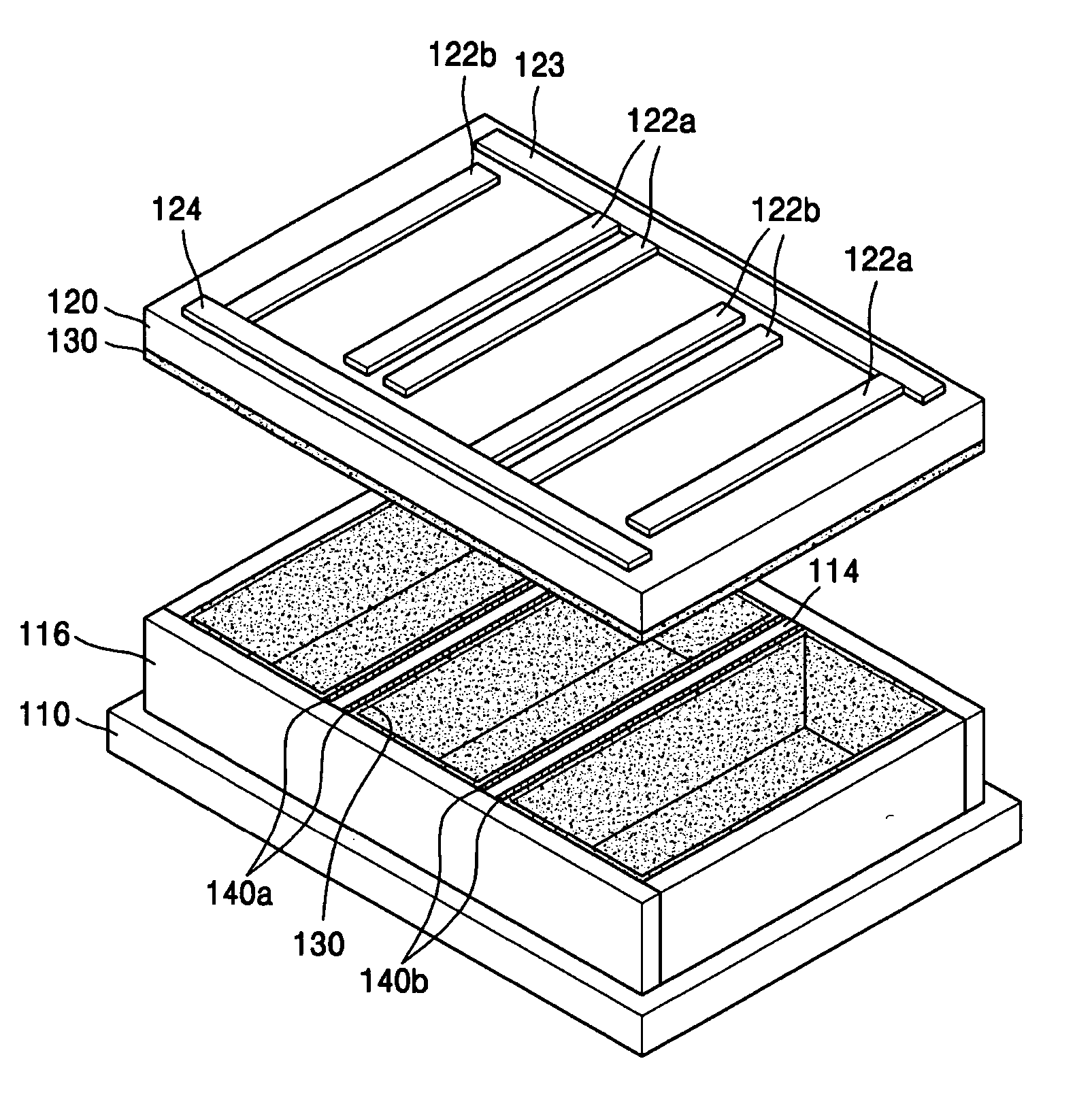
[0034]FIG. 3 is an exploded perspective view of a flat lamp according to an embodiment of the present invention, and FIG. 4 is a partial cross-sectional view of the flat lamp of FIG. 3.

[0035] Referring to FIGS. 3 and 4, a discharge space is formed by disposing a lower substrate 110 and an upper substrate 120 facing each other. Here, the lower substrate 110 and the upper substrate 120 are generally formed of a transparent glass substrate. Frames 116 that seal the discharge space and maintains a predetermined gap between the lower substrate 110 and the upper substrate 120 is formed therebetween. A discharge gas which is a mixture of a Ne gas and a Xe gas is filled in the discharge space.

[0036] A plurality of spacers 114 is disposed parallel to each other between the lower substrate 110 and the upper substrate 120. The sp...


PUM


Abstract

Provided is a flat lamp which includes a lower substrate and an upper substrate that form discharge space therebetween disposed facing each other, a plurality of discharge electrodes formed at least on one of the lower substrate and the upper substrate, a plurality of spacers that form a plurality of discharge cells by defining the discharge space, and disposed parallel to the discharge electrodes between the lower substrate and the upper substrate, a plurality of auxiliary electrodes, to which a voltage is induced by applying a voltage to the discharge electrodes, formed on a surface of the spacers, and a fluorescent layer formed on an inner wall of the discharge cells.

Description

BACKGROUND OF THE INVENTION [0001] Priority is claimed to Korean Patent Application No. 10-2004-0075969, filed on Sep. 22, 2004, in the Korean Intellectual Property Office, the disclosure of which is incorporated herein in its entirety by reference. [0002] 1. Field of the Invention [0003] The present invention relates to a flat lamp, and more particularly, to a flat lamp that can reduce a discharge voltage and improve luminous efficiency. [0004] 2. Description of the Related Art [0005] Flat lamps developed as back-lights for liquid crystal displays (LCD) have evolved into a surface discharge type or a facing discharge type flat lamp type, in which a whole lower portion of the light emitting surface is discharge space. These mark an improvement in consideration of luminous efficiency and uniformity of brightness over a conventional edge-light type or a direct-light type flat lamp, which uses a cold cathode fluorescent lamp. The surface discharge flat lamp has the advantage of a stabl...

Claims


Application Information

Patent Timeline
Patent Type & Authority Applications(United States)
IPC IPC(8): H01J17/16H01J17/00
CPCG02F1/133602H01J65/046H01J65/00H01J61/544H01J3/02H01J61/305
Inventor KIM, GI-YOUNGLEE, SEONG-EUIPARK, HYOUNG-BIN
Owner SAMSUNG CORNING CO LTD
Why Eureka
Try Eureka