Hybrid magnet configuration

Active Publication Date: 2006-03-23
BRUKER BIOSPIN
View PDF10 Cites 16 Cited by
  • Summary
  • Abstract
  • Description
  • Claims
  • Application Information

AI Technical Summary

Benefits of technology

[0039] The invention also concerns a method for operation of the magnet configuration in accordance with the invention, wherein the additional windings are charged in a directed fashion up to the desired operational current values. This facilitates individual adjustment of the magnetic stray field.
[0040] In a particularly preferred variation of the method in accordance with the invention, the additional windings are superconductingly short circuited and their respecti

Problems solved by technology

However, solenoid coils are not suitable for production of homogenous magnetic fields, since this simple geometry has, up to this point, not been capable of compensating for the interfering coefficients h2, h4, . . . . It is therefore conventional in the art to use solenoid coils having one or more notches in order to produce homogenous magnetic fields with such windings.
A substantial disadvantage of utilization of magnet coils having notches which, in practice, are fashioned by rings filled up with a solid material, is that the bordering windings made from superconducting wire can undergo a transition into the normally conducting state in response to the large magnetic forces which lead to friction or other relaxation phenomena in the bordering region.
As a result thereof, an overheating of the normally conducting regions can occur and, in extreme cases, the magnet coil can be destroyed.
This makes, in particular, the production of extremely high magnetic fields difficult or makes the magnetic coil more expensive, since one is forced to limit the current

Method used


Image

  • Hybrid magnet configuration
  • Hybrid magnet configuration
  • Hybrid magnet configuration

Examples


Example

[0051] Table 1 is an embodiment of an inventive magnet configuration with dimensions, current densities and magnetic polarization of the components;

[0052] Table 2 are the field interferences h2z02, h4z04, . . . of the magnet configuration according to Table 2 without field forming device at an axial position z0=0.05 m, relative to the magnetic field H0 produced by the magnet configuration at z=0.

[0053] Table 3 is the average axial position for the attachment of plates onto a cylindrical carrier or support of the field forming device of the magnet configuration in accordance with Table 1;

[0054] Table 4 is the occupation of the iron plates of the field forming device according to Table 3; and

[0055] Table 5 is the theoretical field interferences h2, h4 . . . , of the magnet configuration according to Table 1 with the field forming device according to Tables 3 and 4.

DESCRIPTION OF THE PREFERRED EMBODIMENT

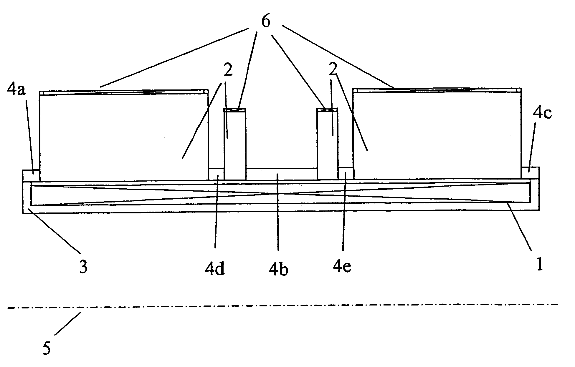
[0056]FIG. 1 shows the principal components of a conventional rotationally sy...


PUM


Abstract

A co-axial magnet configuration for the production of a magnetic field and investigational volume which is suitable for measurement of magnetic resonance has at least one superconducting solenoid coil or solenoid coils which are radially nested within each other, wherein the windings of the solenoid coil(s) in a radial region about the axis of the magnetic configuration are disposed between r1 and r2, wherein r1<r2 is characterized in that the windings are surrounded by at least one rotationally symmetric magnet body made from ferromagnetic material which extends over a radial region between r3 and r4 wherein r3<r4 wherein r2<r3<1.3 r2 and r4>1.3 r3, wherein the rotationally symmetric magnet body or bodies are structured, dimensioned and positioned in such a fashion that the magnetic field is homogenized in the investigational volume and the magnetic fringe field outside the magnet configuration is essentially suppressed to permit the production of strong magnetic fields of high homogeneity without requiring notches in the coil configuration.

Description

[0001] This application claims Paris Convention priority of DE 10 2004 007 291.4 filed Feb. 14, 2004 the entire disclosure of which is hereby incorporated by reference. BACKGROUND OF THE INVENTION [0002] The invention concerns a coaxial magnet configuration for production of a magnetic field in an investigation of volume which is suitable for measurement of magnetic resonance with at least one superconducting solenoid coil or with solenoid coils which are radially nested within each other, wherein the windings of the solenoid coil (s) in a radial region about the axis of the magnet configuration are disposed between r1 and r2 wherein r1>r2. [0003] The magnetic field h(z) as a function of the coordinate z on the axis of a magnet system of this kind can be generally expressed as follows: h(z)=h0+h1z+h2z2+h3z3+h4z4+h5z5+h6z6+ . . . [0004] The term h0 thereby represents the desired position independent and therefore homogenous magnetic field. The additional terms with the coefficient...

Claims


Application Information

Patent Timeline
IPC IPC(8): G01V3/00H01F3/00H01F1/00H01F7/00G01R33/3815G01R33/3873G01R33/3875
CPCG01R33/3815G01R33/3875G01R33/3873
Inventor WESTPHAL, MICHAEL
Owner BRUKER BIOSPIN
Why Eureka
Try Eureka