High loft nonwoven with balanced properties

a non-woven, high loft technology, applied in the direction of woven fabrics, textiles and papermaking, weaving, etc., can solve the problems of high initial loft of fabric with false loft, limited conventional process, and high cross-direction tensile strength of webs, so as to improve strength, improve fire retardancy, and achieve balanced strength properties in machine and cross-direction

Inactive Publication Date: 2006-03-23
SYLVAN CHEM CO
View PDF8 Cites 21 Cited by
  • Summary
  • Abstract
  • Description
  • Claims
  • Application Information

AI Technical Summary

Benefits of technology

[0019] U.S. Pat. No. 5,252,386, issued to Hughes et al. on Oct. 12, 1993, describes a process for making an entangled nonwoven fabric having balanced strength properties in the machine and cross directions and improved fire retardancy. These characteristics are achieved by cross-stretching the entangled fabric after the fabric has been wetted with an aqueous-based fire retardant composition and drying the wetted

Problems solved by technology

For example, a fabric with false loft will have a high initial loft due to excessive voids within the fabric.
This conventional process is limited in that tensile strength of the web in the cross direction is higher than the tensile strength in the machine direction.
Another drawback of the conventional process is that the low melt fibers typically constitute twenty percent (20%) or more of the web, by weight.
These low melt fibers are more expensive than the polyester fibers, adding cost to the product.
A further limitation of the conventional process is that the production rate is limited by the cross-lapper.
That is, the faster the production rate, the more inconsistent the fibers are laid when cross lapped.
Moreover, the cross lapper is incapable of cycling back and forth at a speed sufficient to keep up with the speed of the other production components.
This is particularly a problem for lightweight, nonwoven fabrics wherein inconsistently laid fibers reduce the fabrics' quality and diminishes physical properties of the product.
Disadvantageously, the step of applying resin is also quite slow in comparison to the process speed

Method used

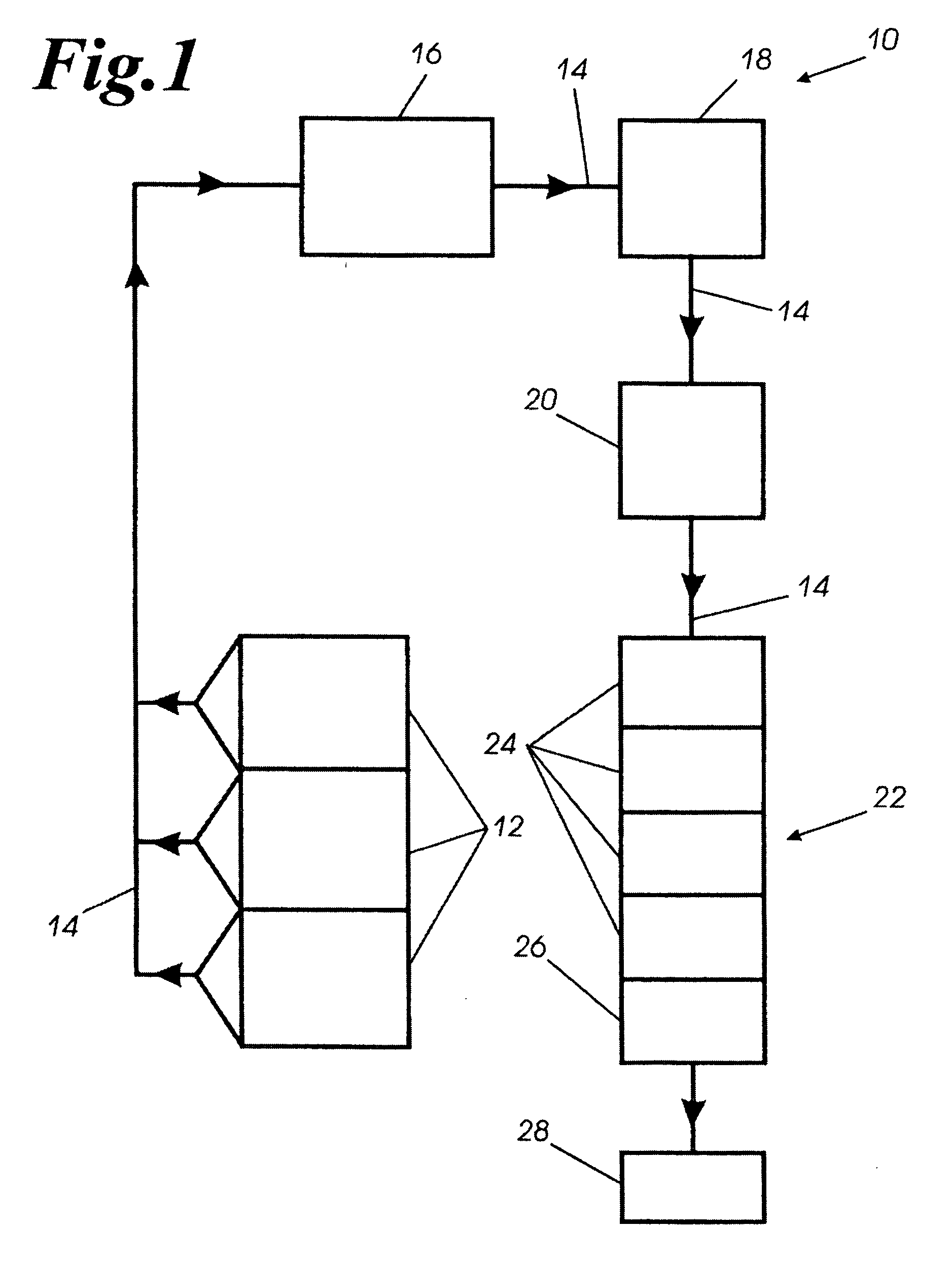

Image

  • High loft nonwoven with balanced properties

Examples


example 1

[0046] Referring to Table 1, the quality of a Control high loft nonwoven fabric and three Sample fabrics are compared. Each of the fabrics had a weight of 0.75 oz / ft2 and a weight percent blend of: 20% 4 dpf (denier per filament) low melt binder fiber, 30% 25 dpf PET, and 50% 15 dpf PET. The Samples were processed with different number of layers, with the Control, First Sample, Second Sample and Third Sample respectively having 2, 2, 3 and 4 layers. In order to maintain the same weight (oz / ft2), the process rate was adjusted, with the Control, First Sample, Second Sample, and Third Sample respectively processed at 1278 lbs / hr, 1775 lbs / hr, 1896 lbs / hr and 1896 lbs / hr.

TABLE 1Percent Loft Recovery for 0.75 oz / ft2 Control and SamplesApplied Load (lbs)Loft (inches)Percent Loft (%)ControlBlend (20% 4 dpf low melt, 30% 25 dpf PET, and 50% 15 dpf PET)Rate: 1278 lbs / hr Weight: 0.75 oz / ft2 Number of Laps: 2Zero1.75100 51.3979.4101.1867.4151.0358.9200.9353.1Load removed1.6896.0(% loft recov...

example 2

[0050] Referring to Table 3, a Control high loft, nonwoven fabric and two Sample fabrics are compared wherein each of the fabrics had a weight of 1.0 oz / ft2 and a weight percent blend of: 20% 4 dpf low melt binder fiber, 30% 25 dpf PET, and 50% 15 dpf PET. The Samples were processed wiith different number of laps, with the Control, First Sample and Second Sample having 3, 3 and 4 laps, respectively. The process rate was adjusted in order to maintain the same weight (oz / ft2), with the Control, First Sample and Second Sample respectively processed at 920 lbs / hr, 1050 lbs / hr and 1100 lbs / hr.

TABLE 3Percent Loft Recovery for 1.0 oz / ft2 Control and SamplesApplied Load (lbs)Loft (inches)Percent Loft (%)ControlBlend (20% 4 dpf low melt, 30% 25 dpf PET, and 50% 15 dpf PET)Rate: 920 lbs / hr Weight: 1.0 oz / ft2 Number of Laps: 3Zero2.82100 52.1475.9101.7562.1151.4350.7201.3 46.1Load removed2.7 95.7(% loft recovery)Sample 1Blend (20% 4 dpf low melt, 30% 25 dpf PET, and 50% 15 dpf PET)Rate: 1050...

example 3

[0054] Because the drafter provides a more balanced fabric (with respect to certain physical properties), it is possible to lower the amount of binder and still achieve good tensile strength properties. Table 5 compares the Control having 20% binder and the Samples each of which had a weight of 1.0 oz / ft2 and a weight percent blend of: 10% 4 dpf low melt binder fiber, 35% 25 dpf PET, and 55% 15 dpf PET.

TABLE 5Loft Recovery for 1.0 oz / ft2 Control and 10% Low MeltBinder Fiber SamplesApplied Load (lbs)Loft (inches)Percent Loft (%)ControlBlend (20% 4 dpf low melt, 30% 25 dpf PET, and 50% 15 dpf PET)Rate: 920 lbs / hr Weight: 1.0 oz / ft2 Number of Laps: 3Zero2.82100 52.1475.9101.7562.1151.4350.7201.3 46.1Load removed2.7 95.7(% loft recovery)Sample 1 (10% Low melt fiber)Blend (10% 4 dpf low melt, 35% 25 dpf PET, and 55% 15 dpf PET)Rate: 1050 lbs / hr Weight: 1.0 oz / ft2 Number of Laps: 3Zero2.41100 51.7673.0101.4359.3151.2551.9201.1146.1Load removed2.2593.4(% loft recovery)Sample 2 (10% Low m...


PUM

PropertyMeasurementUnit
Fractionaaaaaaaaaa
Fractionaaaaaaaaaa
Massaaaaaaaaaa

Abstract

The present invention relates to process for making a light-weight, high loft nonwoven fabric. The process adds a drafter to a conventional nonwoven process in order to increase the production rate. Additionally, the invented process improves the quality of the manufactured fabric by increasing the tensile strength in the machine direction, providing balanced strength in the machine and cross directions, and enhancing resiliency. The process blends polyester fiber with a low melt fiber or low melt bicomponent fiber to form a web. The web is optionally carded and cross lapped before being drafted. Thereafter, the web is heated in an oven having sufficient heat to melt the low melt fiber then cooled to set the properties.

Description

CROSS REFERENCE TO RELATED APPLICATION [0001] This application filed under 37 CFR 1.53(b) is a continuation of U.S. Ser. Number 10 / 449,279 filed on May 30, 2003.BACKGROUND OF THE INVENTION [0002] 1) Field of the Invention [0003] The present invention relates to a high loft having balanced properties and a method of making the same for the production of nonwoven fabric. In particular, the present invention relates to a lightweight, high loft nonwoven fabric in which properties in the machine direction and cross direction such as resiliency (measured in terms of improved loft), and improved tensile strength are more uniform. Additionally, a process for making the high loft nonwoven is unique in that a drafter machine is employed, thereby increasing the efficiency of the production process. [0004] 2) Prior Art [0005] High loft nonwoven fabrics are used in a wide variety of applications, for example, in indoor and outdoor furniture, bedding such as mattresses, and quilting. As such, the...

Claims


Application Information

Patent Timeline
IPC IPC(8): D04H13/00D04H1/54D04H1/00D04H3/14D04H1/60D04H1/70
CPCD04H1/54D04H1/70D04H1/60Y10T442/60Y10T442/637Y10T442/69Y10T442/692Y10T442/696Y10T442/697Y10T442/698
Inventor MCGUIRE, SHERI L.
Owner SYLVAN CHEM CO
Why Eureka
Try Eureka