Stent and method for manufacturing the stent

a stent and manufacturing method technology, applied in the field of helical stents, can solve the problems of insufficient coverage of all the use of a stent that is very difficult to manufacture, and the inability to adequately cover the entire tissue within the bounds of the stent, so as to improve the resistance to the passage of emboli, improve the flexibility and resistance to buckling, and improve the effect of stent quality

Active Publication Date: 2006-03-23
ANGIOMED GMBH & CO MEDIZINTECHNIK KG
View PDF79 Cites 32 Cited by
  • Summary
  • Abstract
  • Description
  • Claims
  • Application Information

AI Technical Summary

Benefits of technology

[0014] It is accordingly an object of the invention to provide a helical stent and a method for manufacturing the stent that overcome the hereinafore-mentioned disadvantages of the heretofore-known devices of this general type and that improves helical machined-tube stents, whether balloon-expanded or self-expanding.
[0015] The self-expended stent of the present invention is suitable for use in peripheral arteries, the biliary tree, and other body lumens. In particular, it will be most advantageous for use in arteries where flexure is an important factor, such as iliac arteries and carotid arteries. It is not traditional for cardiologists to use self-expanding stents in coronary arteries or coronary bypass grafts. Nonetheless, the present invention is especially suitable for the diffuse disease often encountered in these locations. Also, because of the high total surface area of the present configuration, the stent is particularly suitable for the application of drug-eluting coatings intended to reduce restenosis or for other therapies. Specifically, the stent according to the present invention allows virtually all tissue within the coverage area of the stent to be in the elution areas. In particular, the stent provides tissue coverage so that no element of wall tissue is more than 350 microns to 400 microns away from the nearest strut. Such a configuration assures a short diffusion path from a strut covered with a drug-eluting agent to any portion of the tissue.

Problems solved by technology

Other manufacturing techniques have been proposed, such as vacuum or chemical deposition of material or forming a tube of machined flat material, but those “exoti” methods have not been widely commercialized.
However, Palmaz teaches use of a stent that is very difficult to manufacture because of the great number of very small openings in the covering film or “web.”
Because prior art stent designs have large gaps between stent parts, drug elution about these parts does not adequately cover all of the tissue within the bounds of the stent.
In his report “Era of Drug-Coated and Drug-Eluting Stents” (TCT 2002), G. Grube states that the typical open-cell configuration gives poor distribution of the drug into the arterial wall because of the large open gaps when the stent is situated in a bend of the artery.

Method used


Image

  • Stent and method for manufacturing the stent
  • Stent and method for manufacturing the stent
  • Stent and method for manufacturing the stent

Examples


Embodiment Construction

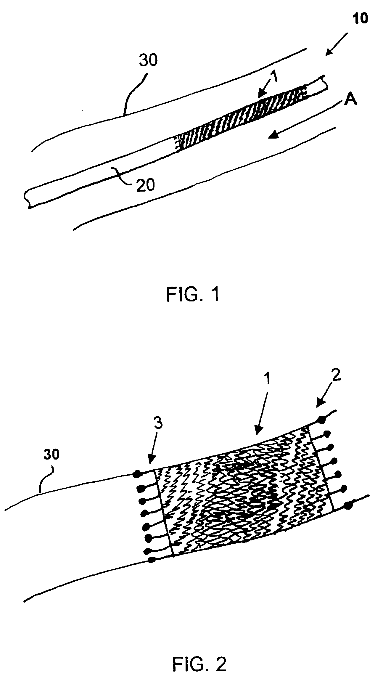
[0055] Referring now to the figures of the drawings in detail and first, particularly to FIG. 1 thereof, there is shown is a helical stent 1 according to the present invention fitted on a delivery catheter 20 of an exemplary delivery system 10. The helical stent 1 is about to be implanted in a vessel 30. The helical stent 1 is in its unexpanded state and loaded into / onto the delivery system 10 that has traveled to an implantation site. FIG. 2 illustrates the helical stent I implanted in the vessel 30 after being expanded, whether by a balloon of the catheter 20 or by self-expansion due to a shape memory of the material of the stent 1.

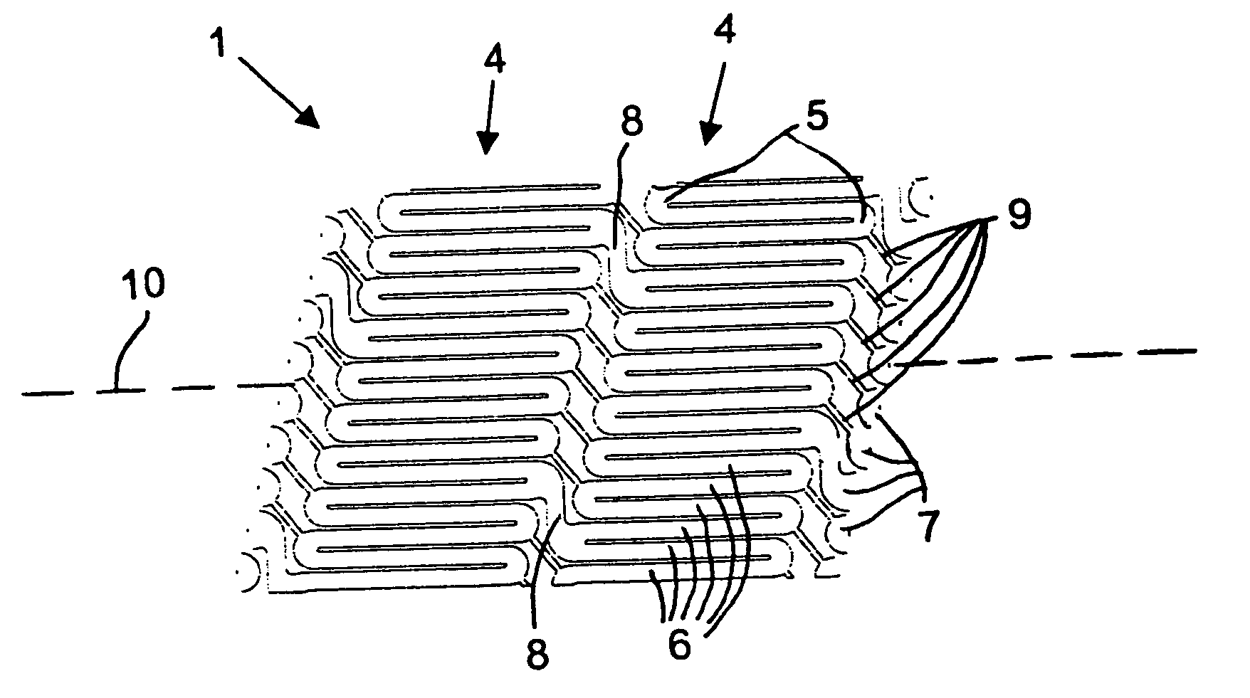
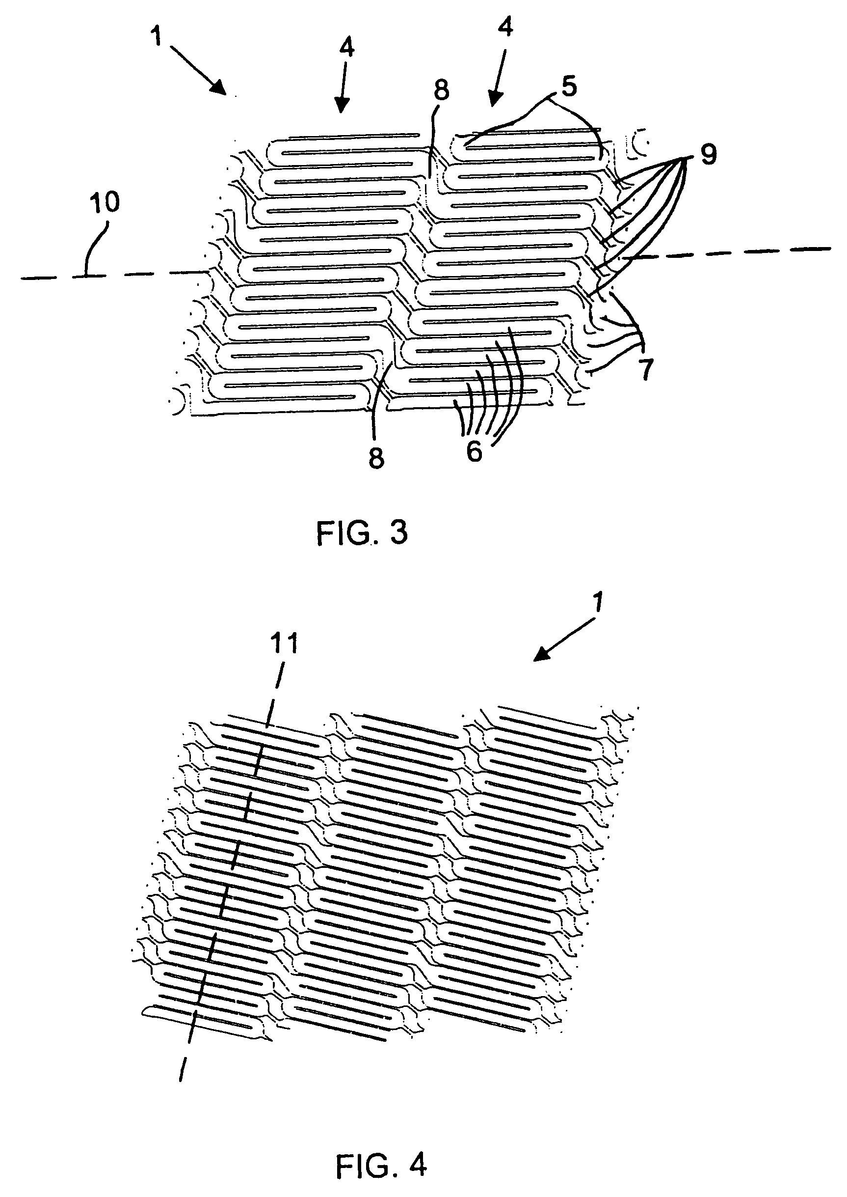
[0056] The helical stent 1 has proximal 2 and distal 3 ends—defined by a blood flow direction A. The helix of the stent 1 can be a single coil with one start at the proximal end that winds all the way to the distal end. Such a configuration is possible with the present invention because the helical stent 1 has very short struts, which will be explained...


PUM


Abstract

A stent includes a stent body having a circumference, a diameter of between approximately 4 mm and approximately 12 mm, in particular, 8 mm, and a length of between approximately 10 mm and approximately 250 mm, in particular, 150 mm, and struts disposed helically about the circumference in turns. Substantially circumferentially oriented connecting bridges connect respectively adjacent ones of the turns. A method for manufacturing a helical stent includes the steps of providing a stent body with struts disposed about the circumference thereof in turns and with bridges connecting the struts in adjacent turns. The stent body is expanded and, thereafter, some of the bridges, in particular, sacrificial bridges, are removed.

Description

CROSS-REFERENCE TO RELATED APPLICATION [0001] This application claims the priority, under 35 U.S.C.§ 119, of U.S. Provisional Patent Application No. 60 / 606,261 filed Sep. 1, 2004, the entire disclosure of which is hereby incorporated herein by reference in its entirety.STATEMENT REGARDING FEDERALLY SPONSORED RESEARCH OR DEVELOPMENT [0002] n / a FIELD OF THE INVENTION [0003] The invention lies in the field of vascular stents. In particular, the invention is in the field of helical stents for peripheral arteries, the biliary tree, and other body lumens. [0004] Stents have been developed for use in various lumens of the body, including the biliary tree, venous system, peripheral arteries, and coronary arteries. Stents are used to open or hold open a lumen that has been blocked (occluded) or reduced in size (stenosed) by some disease process, such as atherosclerosis or cancer. Previously developed stents for use in the biliary, venous, and arterial systems have been of two broad classes: ...

Claims


Application Information

Patent Timeline
Patent Type & Authority Applications(United States)
IPC IPC(8): A61F2/88
CPCA61F2/848A61F2/88A61F2/91A61F2/915A61F2250/0098A61F2002/91533A61F2002/91558A61F2002/9665A61F2002/0864A61F2/844A61F2002/91541A61F2002/91583
Inventor BALES, THOMAS O.SLATER, CHARLES R.JAHRMARKT, SCOTT L.
Owner ANGIOMED GMBH & CO MEDIZINTECHNIK KG
Why Eureka
Try Eureka