

Method for testing of a combined dynamic positioning and power management system
a power management system and dynamic positioning technology, applied in the direction of testing/monitoring control systems, process and machine control, instruments, etc., can solve the problems of not being able to test the functionality and performance of the power system in a systematic and comprehensive manner, and not being able to accurately simulate the pms system with available methods and technology,
- Summary
- Abstract
- Description
- Claims
- Application Information
AI Technical Summary
Benefits of technology
Problems solved by technology
Method used
Image

Examples
first embodiment
of the Invention
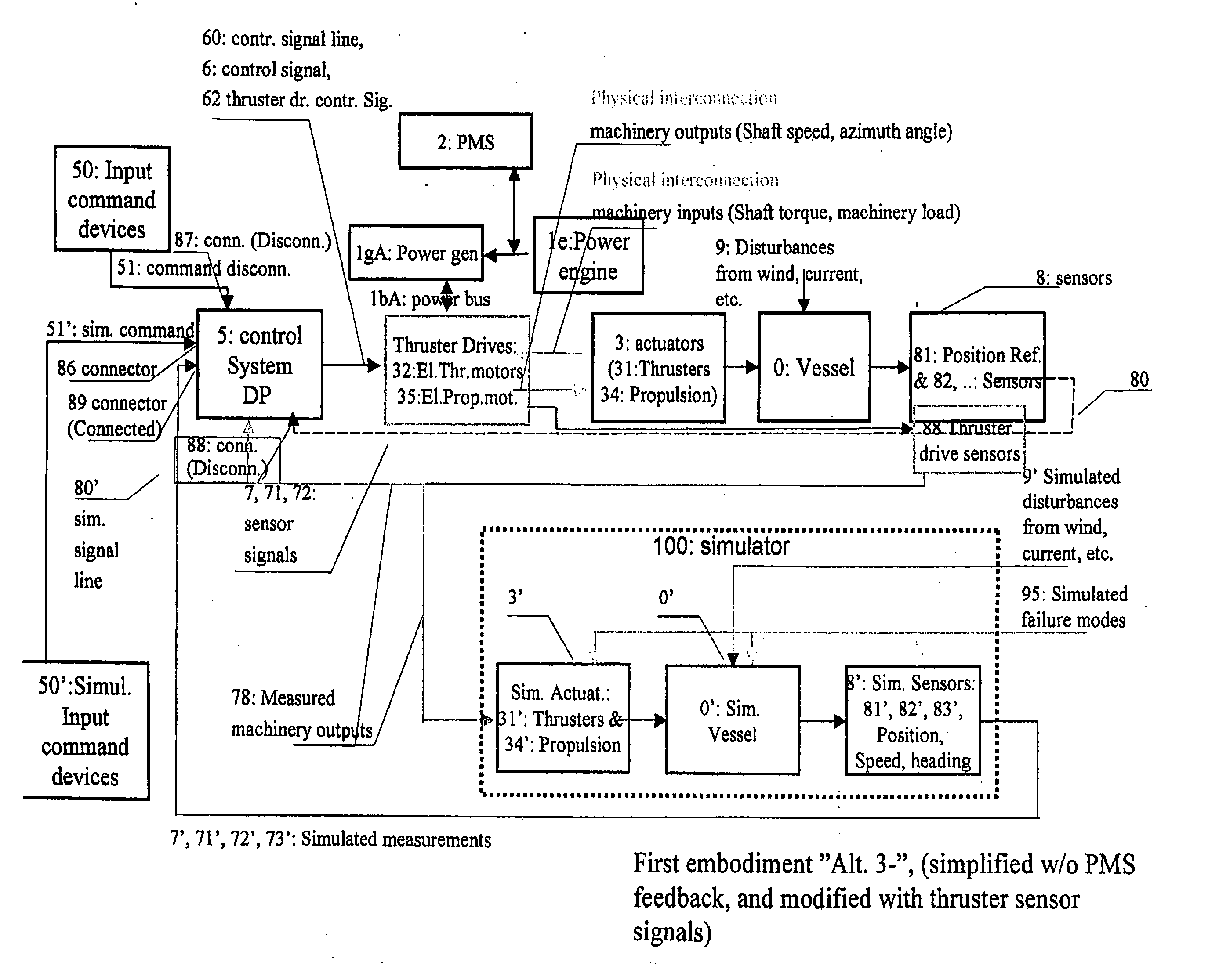
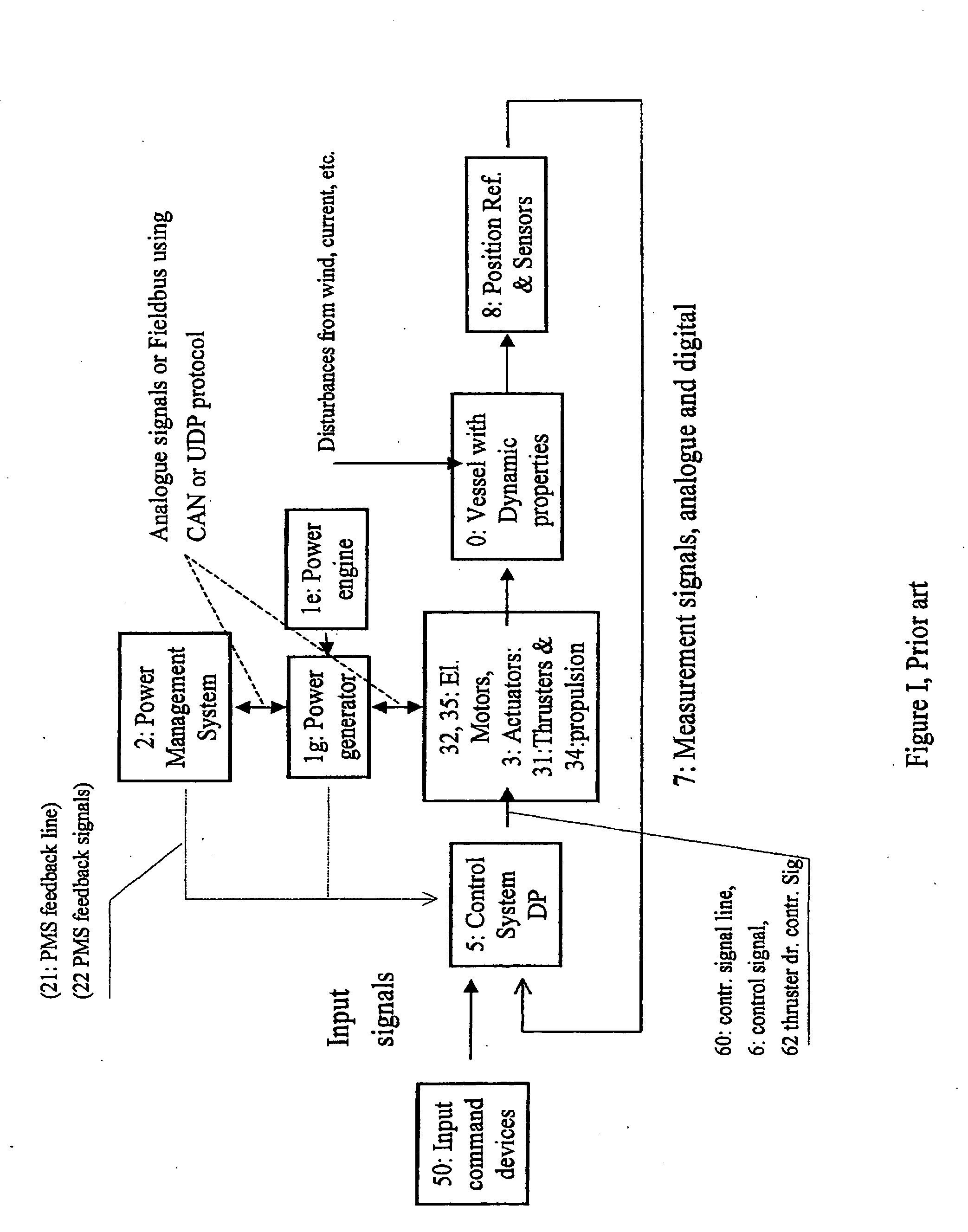
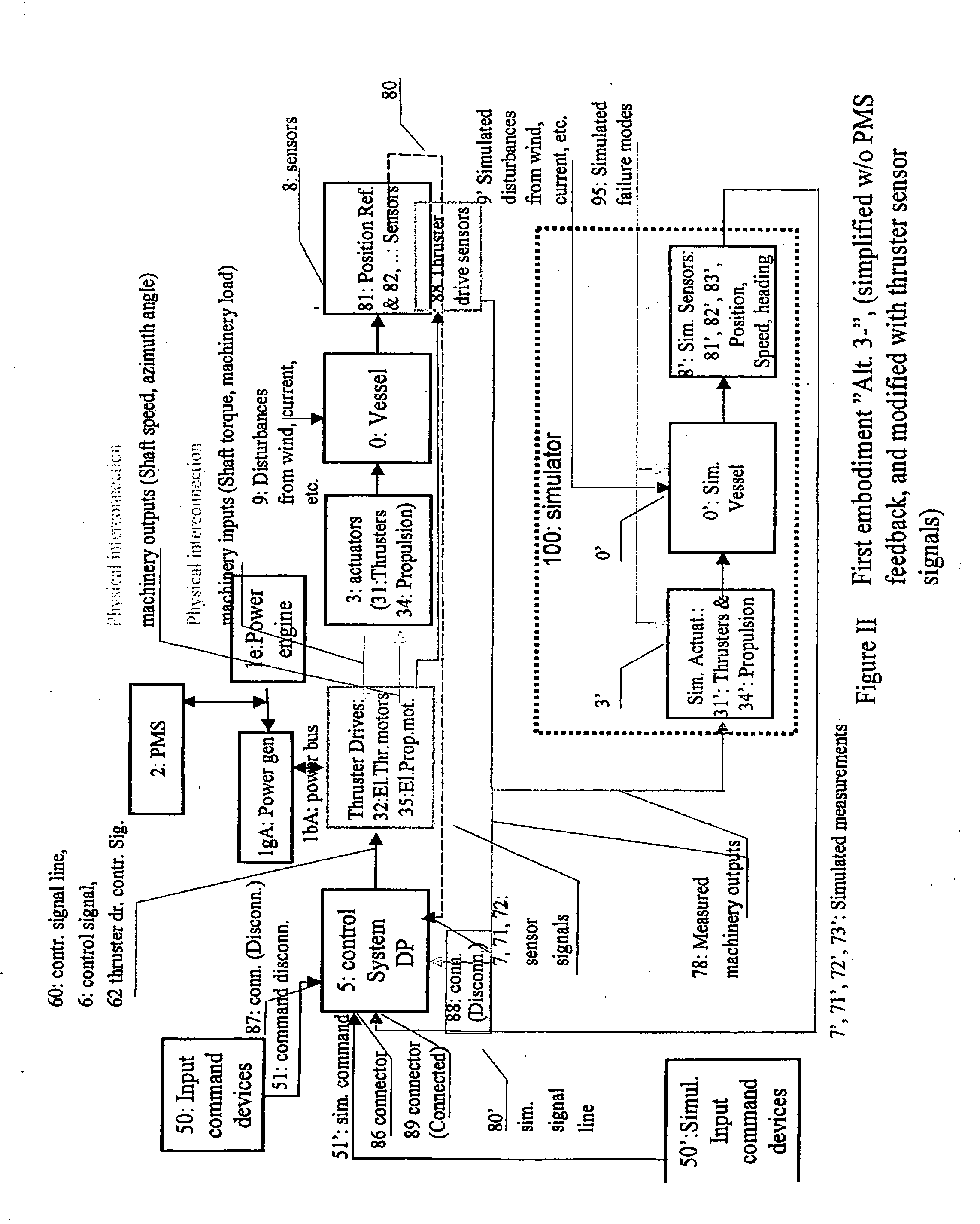
[0090] The first embodiment of the invention illustrated in Fig. II is a hardware-in-the-loop (“HIL”)-test of a system comprising the DP control system (5), the thruster drive motor (32) system, the electrical power system (1), and the power management system (2). Because the thruster drive system (32) drives the actual thruster (31) units that in turn drive the vessel (0), the load on the thruster drive system (32) may be realistic. Compared to prior art in which a DP control system has been tested in HIL testing, the advantage of the present invention is that the thruster drive system (32), the electrical power system (1), and the power management system (2) are also tested in a hardware-in-the-loop configuration in combination with the DP control system (5). This is important as the coupling between the DP control system (5) and the power management system (2) may lead to unforeseen problems that may lead to potentially dangerous or costly situations involving loa...
second embodiment
of the Invention
[0092] The second embodiment of the invention as illustrated in Fig. III has the same advantages as the basic embodiments, but in addition feedback signals (72) from the thruster drive (32) and feedback signals (22) from the real power management system (2) to the DP control system (5) will be included in the test. The inclusion of these feedback interconnections are common in DP system and increases the complexity of the combined dynamics of the DP system and the power management system, and testing is of the combined system in a HIL configuration may be of great value.
third embodiment
of the Invention
[0093] The third embodiment of the invention illustrated in Fig. IV is a hardware-in-the-loop test of a system comprising the DP control system (5), the thruster drive motor system (32), the electrical power system (1), and the power management system (2). In this embodiment the simulator (100) includes models of the thruster drive system (32′), the electrical power system (1′) and the power management system (2). The advantage of this solution is that there is no need to access the thruster drive sensors (88), which means that this solution may lead to a simpler interfacing so that the preparations before the testing may take less time than the first embodiment and the second embodiment of which the test system must be interfaced to the thruster drive sensors.
[0094] Compared to the first embodiment and the second embodiment this third embodiment has the possible disadvantage of having to include simulation modules for the thruster electrical drive system (32′), the...
PUM
 Abstract
Description
Claims
Application Information