Unmanned aerial vehicle apparatus, system and method for retrieving data

a technology for aerial vehicles and data, applied in the field of unmanned aerial vehicles, can solve the problems of inability to collect data remotely, inability to use such instruments, and large power sources, etc., and achieve the effects of increasing maintenance costs, transferring large amounts of data quickly, and inconvenient us

Inactive Publication Date: 2005-03-15
FRINK BENTLEY D
View PDF13 Cites 293 Cited by
  • Summary
  • Abstract
  • Description
  • Claims
  • Application Information

AI Technical Summary

Benefits of technology

Another great application for the data retrieval system of the present invention is the collection of utility meter data, such as electric meter watt-hour readings whenever such meters are located in rural or isolated areas. Urban data collection is sometimes collected using vans equipped with wireless transceivers that automatically read data from transceiver equipped utility meters. This may be an appropriate solution for collecting utility data in urban areas where meter density can be as high as thousands of meters per square mile, but it is a very inefficient and costly way to collect data from rurally located utility meters that can number less than ten per square mile. Another factor adding to unacceptable cost and inefficiency, with regard to surface vehicle retrieval of utility meter data in rural areas, results from the lack of good road infrastructure. Driving a data collection route on unpaved or poorly maintained roads can result in damaged vehicles and increased maintenance costs. Furthermore, after adverse weather events such as floods or heavy snow, it may not be possible to use transceiver equipped surface vehicles to read meters in a timely fashion even in urban areas. Fortunately, the present invention is capable of flying over surface obstacles such as flooded out roadways without any interruption to the data retrieval process.
Furthermore, the present invention is ideally suited to take advantage of a newly legalized form of radio communication known by industry as ultra-wideband (UWB) radio. Ultra-wideband communication systems transmit information using electromagnetic impulses without using a radio frequency carrier. Presently, the FCC restricts UWB transmissions to extremely low power emission, resulting in a range limit of only a few hundred meters and unfortunately UWB receivers are susceptible to traditional narrow band transmitters common to urban areas. Nevertheless, UWB transmitters and receivers combined with the present invention make a powerful combination. The reason is UWB has the ability to transfer large amounts of data quickly due to its large bandwidth. Moreover, UWB systems employ transmitters and receivers that consume far less power than traditional transmitters and receivers making then very attractive for long duration field deployment. However, before the present invention data retrieval from UWB systems located in hard to get to places was impractical. An added benefit of combining a UWB system with the present invention is that the UWB system can also function as a low altitude radar altimeter. Similarly, because UWB also has a short-range geo-location capability, the UWB system could be employed as an automated landing system at an airfield equipped with a compatible UWB system. Finally, the communication need not be limited to radio frequency systems. An alternative can be a light beam communication system such as a broad beam laser, etc.

Problems solved by technology

Use of such instruments is limited, however, by the difficulty or inconvenience in initially placing the instruments at the location required for collection of the relevant data, and in the subsequent retrieval of collected data with the desired frequency.
However, transmission of data requires costly radio equipment, and a large power source.
As a result, remote collection of data, until now, has been cost prohibitive for most applications.
While retrieval of remote field data by way of satellite is appropriate in some cases, it is not practical or even possible for a large number of data retrieval sessions.
The fact is satellite data retrieval is limited by at least three considerable constraints.
One constraint is uplink time allocations that demand relatively expensive very precise time keeping components that must be monitored and adjusted frequently.
Furthermore, there are a limited number of time slots available; therefore, users must gain an assigned time slot through a slow bureaucratic approval process.
Worse still, satellites are distant and require significant amounts of power from the remote ground-based station in order to communicate effectively.
Large power budgets require large heavy expensive batteries usually augmented by even more expensive and fragile solar arrays.
Cellular data phones are another data retrieval option that is far from being an ideal solution.
However, when considered for use as data retrieval devices for collecting data from remote locations, cellular systems fall well short of being a practical solution in many cases.
Moreover, even in cellular coverage areas, data retrieval using cellular technology remains impractical for a significant number of ground-based data collection sites.
Even though cellular transmitters require less power budget than satellite uplinks, the cost of equipping every desired data site with a cellular phone and rate plan is prohibitive in many cases.

Method used


Image

  • Unmanned aerial vehicle apparatus, system and method for retrieving data
  • Unmanned aerial vehicle apparatus, system and method for retrieving data
  • Unmanned aerial vehicle apparatus, system and method for retrieving data

Examples


Embodiment Construction

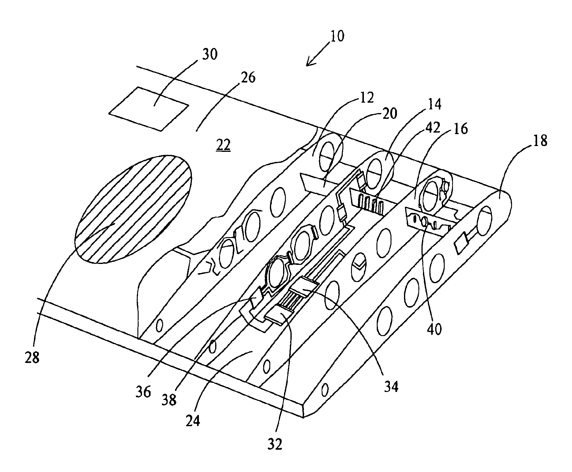
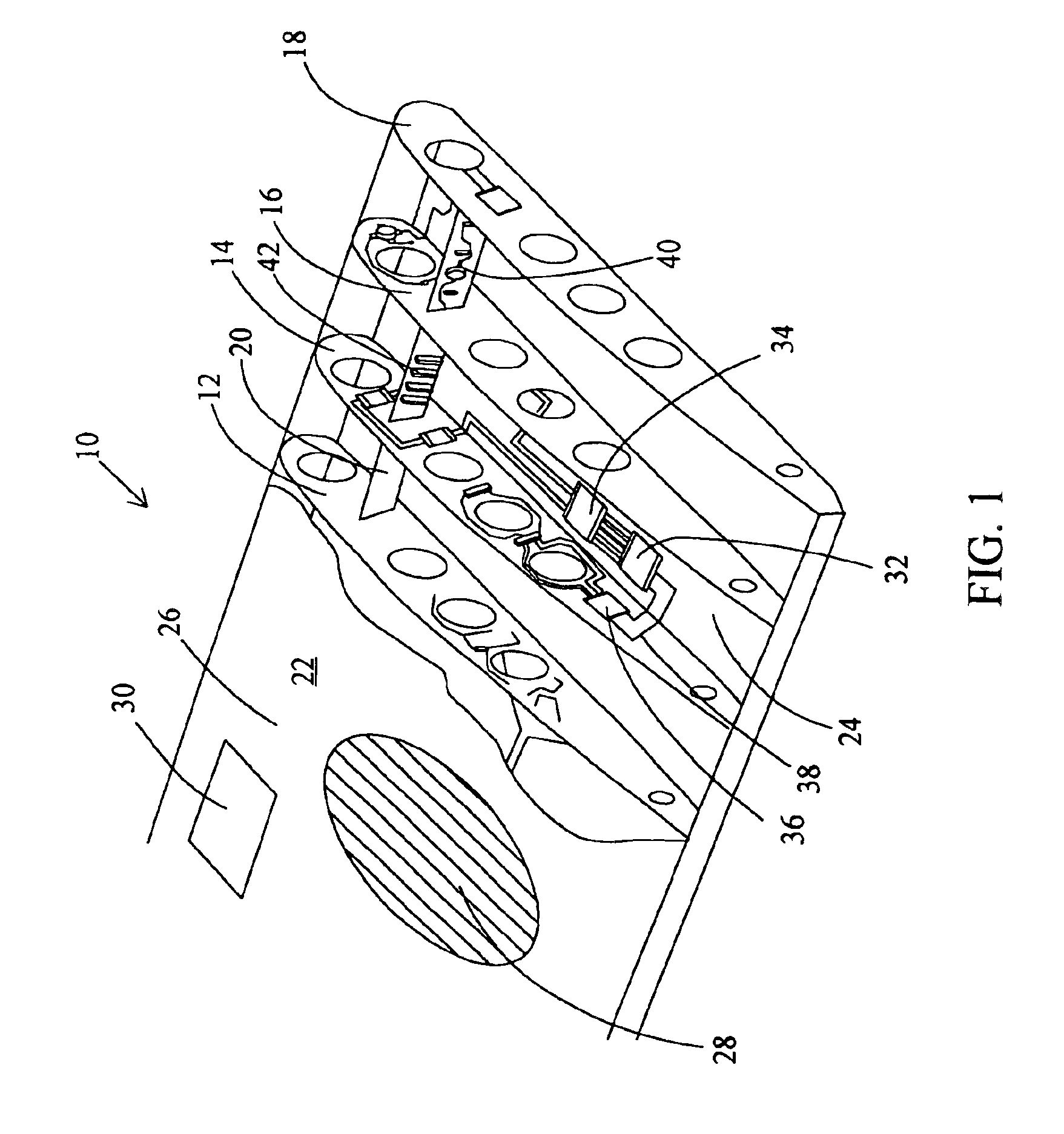
FIG. 1 depicts a cut-away perspective view of a wing according to the present invention. The wing, generally 10 includes ribs 12, 14, 16 and 18 that are mechanically connected by a spar 20. An outer-skin 22 covers the surface of wing 10. Outer-skin 22 has an inner surface 24 and an outer surface 26. Outer surface 26 can include very low profile circuits like a micro-patch antenna 28 and an organic light-emitting diode display 30. Inner surface 24 of outer-skin 22 can include higher profile circuit components such as integrated circuits 32 and 34. Wing rib 14 includes an integrated circuit 36 electrically connected by conductive trace 38. Wing spar 20 is shown having circuitry 40 including memory sockets 42.

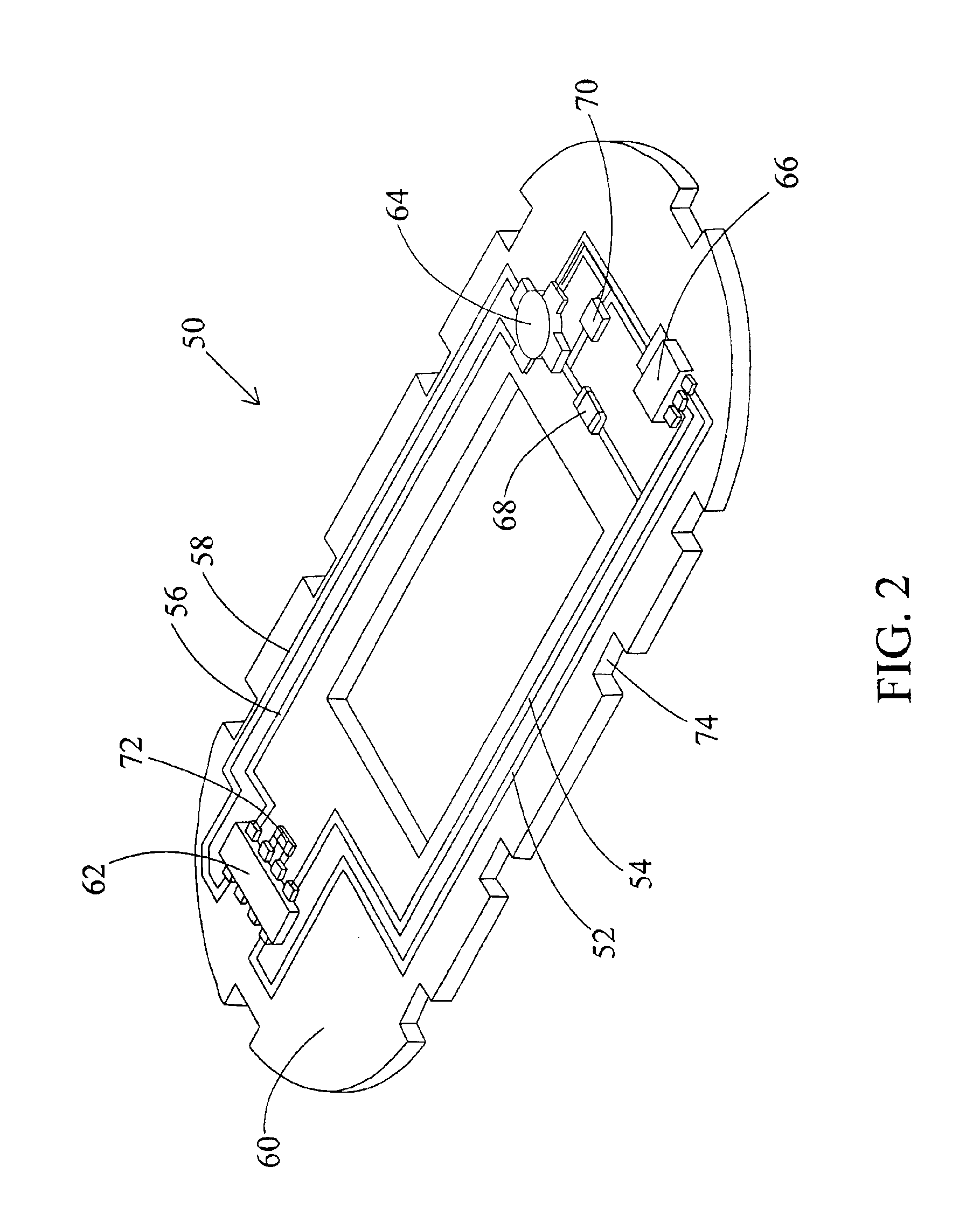
FIG. 2 depicts an airframe structural element useful as a fuselage bulkhead, generally 50. Bulkhead 50 is fabricated according to the present invention. Circuit traces 52, 54, 56, and 58 are adhered to a substrate 60. A surface mount technology packaged integrated circuit 62 is el...


PUM


Abstract

The present invention relates to a system for retrieving data from remote difficult to reach terrain, such as wilderness areas, etc. and in particular to a system comprised of one or more surface based data collectors in communication with one or more wireless transceivers adapted to transmit the collected data to an unmanned aerial vehicle adapted to fly within a predetermined distance from the data collector and receive data collected therefrom. The present invention further relates to an unmanned aerial vehicle adapted to fly a flight pattern relative to a moveable surface object or for controlling the position of a moveable surface object relative to the flight path of the unmanned aerial vehicle. Finally, the present invention relates to an improved unmanned aerial vehicle having airframe structural elements with electrical circuits adhered to the surfaces of the structural elements.

Description

BACKGROUND OF THE INVENTIONField of the InventionThe present invention relates to an unmanned aerial vehicle, in particular, to an unmanned aerial vehicle apparatus suitable for retrieving data collected in remote or hazardous locations.Description of the Prior ArtGround-based instruments are currently used to collect a variety of information. These instruments are used, for example, to collect environmental data, including information concerning air and water quality, as well as water levels in wetlands studies. Other examples are sensors for measuring or detecting soil moisture, dissolved oxygen, biological activity and pH. Numerous opportunities exist for collection of other types of data. Use of such instruments is limited, however, by the difficulty or inconvenience in initially placing the instruments at the location required for collection of the relevant data, and in the subsequent retrieval of collected data with the desired frequency.In environmental studies, for example, ...

Claims


Application Information

Patent Timeline
Patent Type & Authority Patents(United States)
IPC IPC(8): B64C1/00B64C1/06B64C1/10B64D47/02B64D47/00B64C39/00B64C39/02H05K1/02H05K1/18
CPCB64C1/00B64C39/024B64D47/02H05K1/02B64C2201/021B64C2201/044B64C2201/086B64C2201/104B64C2201/187B64C2201/145B64C2201/165H05K1/181H05K2201/09145B64C2201/125A01K79/00B64U50/11B64U70/60B64U30/10B64U10/25B64U2101/35B64U2201/104B64U50/13
Inventor FRINK, BENTLEY D.
Owner FRINK BENTLEY D
Why Eureka
Try Eureka