

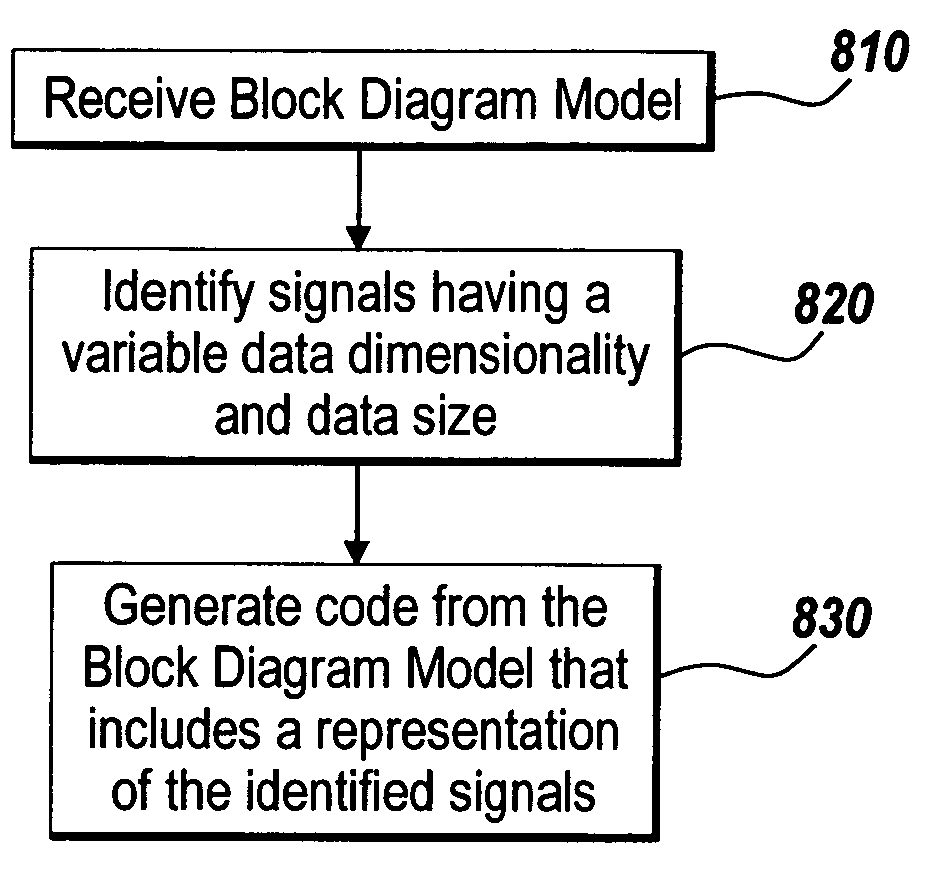
Generation of code from a graphical model
a graphical model and code generation technology, applied in the field of data processing, can solve the problems of insufficient use of dynamic dimensioning in the design of a graphical block diagram model, the inability to design the implementation of a model having one or more signals, and the inability to use dynamic dimensioning
- Summary
- Abstract
- Description
- Claims
- Application Information
AI Technical Summary
Benefits of technology
Problems solved by technology
Method used
Image

Examples
example i
[0115] Blob processing for video signals. For example, the monitoring and tracking of people around an ATM machine, an airport, or a secure entrance to a building or area of a building. The number of people being tracked varies as they enter and leave the scene. Similar problems occur with other tracking applications, such as radar and sonar.
example ii
[0116] Simulink® vectors are used to represent actual data packets specified in a communication standard. Some of these packets have a variable length. For example, the packet length of PLCP (physical layer convergence procedure) in 802.11b / a / g and 802.16 is determined dynamically at the media access control (MAC) and physical (PHY) layer (MAC / PHY) interface, and its value is stored in the packet header.
example iii
[0117] A radar system can dynamically change its transmitted pulse burst length to adjust its range and Doppler resolutions. Accordingly, the data vector length for each pulse can vary during the simulation. This requires variable signal length support from the model. The radar system can also change the number of targets it is tracking. This requires the model to allow the number of vectors / channels to change during simulation.
PUM
 Abstract
Description
Claims
Application Information