Gas pressure regulator having a vibration damping abutment

Inactive Publication Date: 2006-03-30
LUXEMBOURG PATENT CO SA
View PDF5 Cites 26 Cited by
  • Summary
  • Abstract
  • Description
  • Claims
  • Application Information

AI Technical Summary

Benefits of technology

[0011] In order to increase the damping effect there may be provided on the surface of the damping rib, which cooperates with the actuating shaft, a friction facing of rubber or another material having a high coefficient of friction. The regulator housing and the actuating shaft as well as th

Problems solved by technology

In the known gas pressure regulators of this type vibrations of the movable regulator parts in the open condition of the regulator have been encountered, producing during operation of the regulator a rattli

Method used


Image

  • Gas pressure regulator having a vibration damping abutment
  • Gas pressure regulator having a vibration damping abutment
  • Gas pressure regulator having a vibration damping abutment

Examples


Embodiment Construction

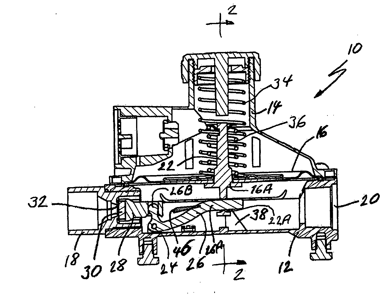
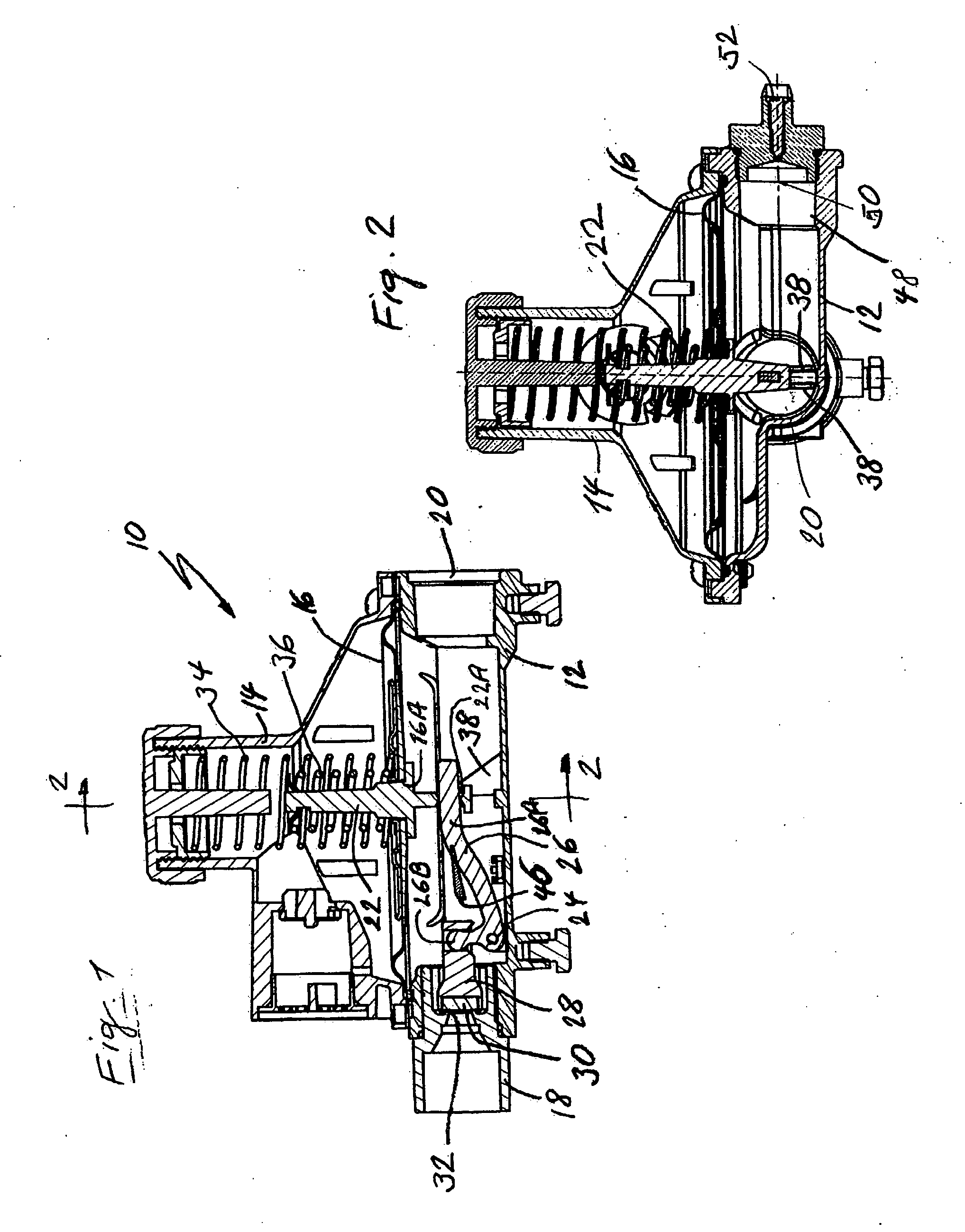
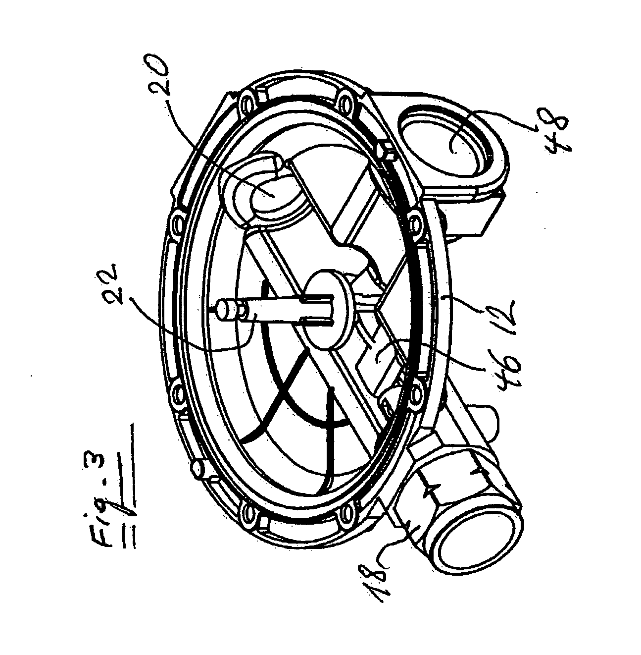
[0021] The gas pressure regulator 10 shown in FIG. 1 has a housing consisting of a lower housing part 12 and upper housing part 14. A diaphragm 16 is tightly clamped between the lower housing part 12 and the upper housing part 14. The lower housing part 12 has in inlet opening into which an inlet connector 18 is threadably engaged. Positioned diametrally opposite the inlet connector 18 is an outlet opening 20 to which a consumer supply line (not shown) may be connected.

[0022] The regulator 10 has a regulator linkage consisting of an actuating shaft 22 received in a central through opening 16A of the diaphragm 16 and fixedly attached thereto, a lever 26 pivotably mounted at 24 to the lower housing part 12, and a piston 28 provided with a seal 30 which engages a seat 32 of the inlet connector in the closed position of the regulator. The actuating shaft 22 has a lower portion provided under the diaphragm 16 and an upper portion extending through the diaphragm into the upper housing pa...


PUM


Abstract

A gas pressure regulator has in the regulator housing (12) a damping abutment (38) adapted to be engaged, in open position of the regulator, by an actuating shaft (22) fixed to a regulator diaphragm (16) for damping vibrations of the regulator mechanism.

Description

[0001] This application claims the benefit under 35 U.S.C. § 119 of European Patent Application No. EP 04104800.0 filed 30 Sep. 2004. BACKGROUND OF THE INVENTION [0002] 1. Field of the Invention [0003] The invention relates to a gas pressure regulator having a regulator housing and a regulator mechanism disposed within the regulator housing and comprising a spring-loaded diaphragm which is adjustable against the spring force by the gas pressure to be regulated, and a regulator linkage including an actuating shaft fixed to the diaphragm, and a regulator piston which is adjustable by the actuating shaft with respect to a regulator seat. [0004] 2. Description of the Prior Art [0005] Gas pressure regulators are known in the state of the art and are commonly used as gas pressure reducing valves in domestic gas supply systems. In the known gas pressure regulators of this type vibrations of the movable regulator parts in the open condition of the regulator have been encountered, producing ...

Claims


Application Information

Patent Timeline
IPC IPC(8): G05D11/00
CPCG05D16/0691G05D16/02G05D16/0686Y10T137/261Y10T137/783Y10T137/7831
Inventor SCHMIDT, J.SCHNEIDER, V.
Owner LUXEMBOURG PATENT CO SA
Why Eureka
Try Eureka