Passive method and apparatus for inducing mode conversion

a mode conversion and mode conversion technology, applied in the field of mode conversion inducing optical waveguides, can solve the problems of electrical failure and performance drift, two outputs that are out of phase with each other, and require excessive dc voltag

Active Publication Date: 2006-03-30
OPTELIAN ACCESS NETWORKS
View PDF3 Cites 26 Cited by
  • Summary
  • Abstract
  • Description
  • Claims
  • Application Information

AI Technical Summary

Benefits of technology

[0014] It is an object of the present invention to obviate or mitigate at least one disadvantage of previous mode converters and polarization modulators.

Problems solved by technology

However, if the propagation speed along the axes is different, the two resulting outputs will be out of phase with each other.
When acting as a simple mode converter, this system has the drawback of requiring excessive DC voltage, whereas other converters can be passive, and thus less prone to electrical failure and performance drift.
Systems such as those illustrated in FIGS. 5, 6 and 7, though offering passive mode conversion, do not provide polarization modulation, and require sophisticated manufacturing techniques to achieve a specific, repetitive pattern that induces sufficient birefringence and axes rotation.
Other mode converters employ internal repetitive structures to effect a rotation of the principal axes, and as a result are equally difficult, if not more difficult, to produce.
As noted above, passive mode converters of this design function only over a narrow optical bandwidth, and are inefficient when used in electro-optic modulation.
The inefficiency arises from the fact that in each waveguide section, the principal axes are not aligned closely to 45° and as a result the electro-optic effect is not acting fully in the same direction as the principal axes.
The mode converter of FIG. 7 provides some degree of axes rotation, and has a static birefringence that is useful for passive mode conversion, but does not provide a mechanism to modulate the polarization.

Method used


Image

  • Passive method and apparatus for inducing mode conversion
  • Passive method and apparatus for inducing mode conversion
  • Passive method and apparatus for inducing mode conversion

Examples


Embodiment Construction

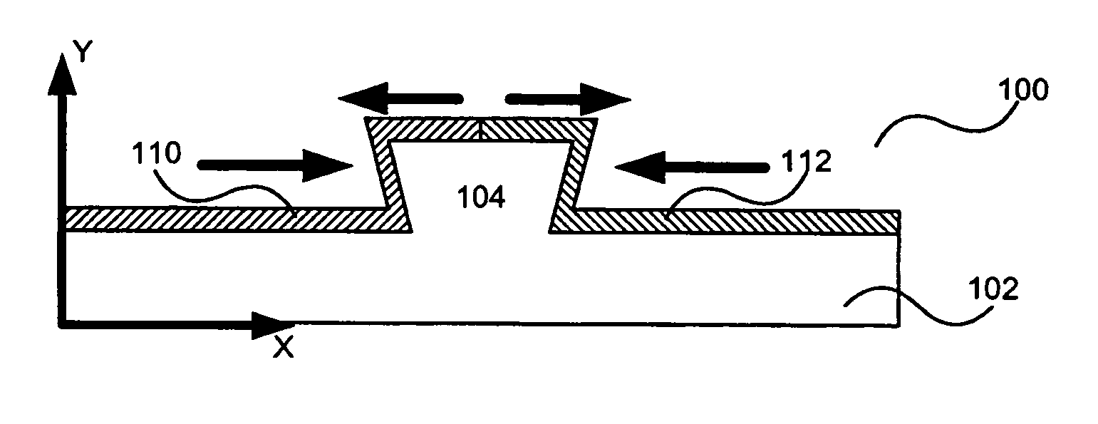
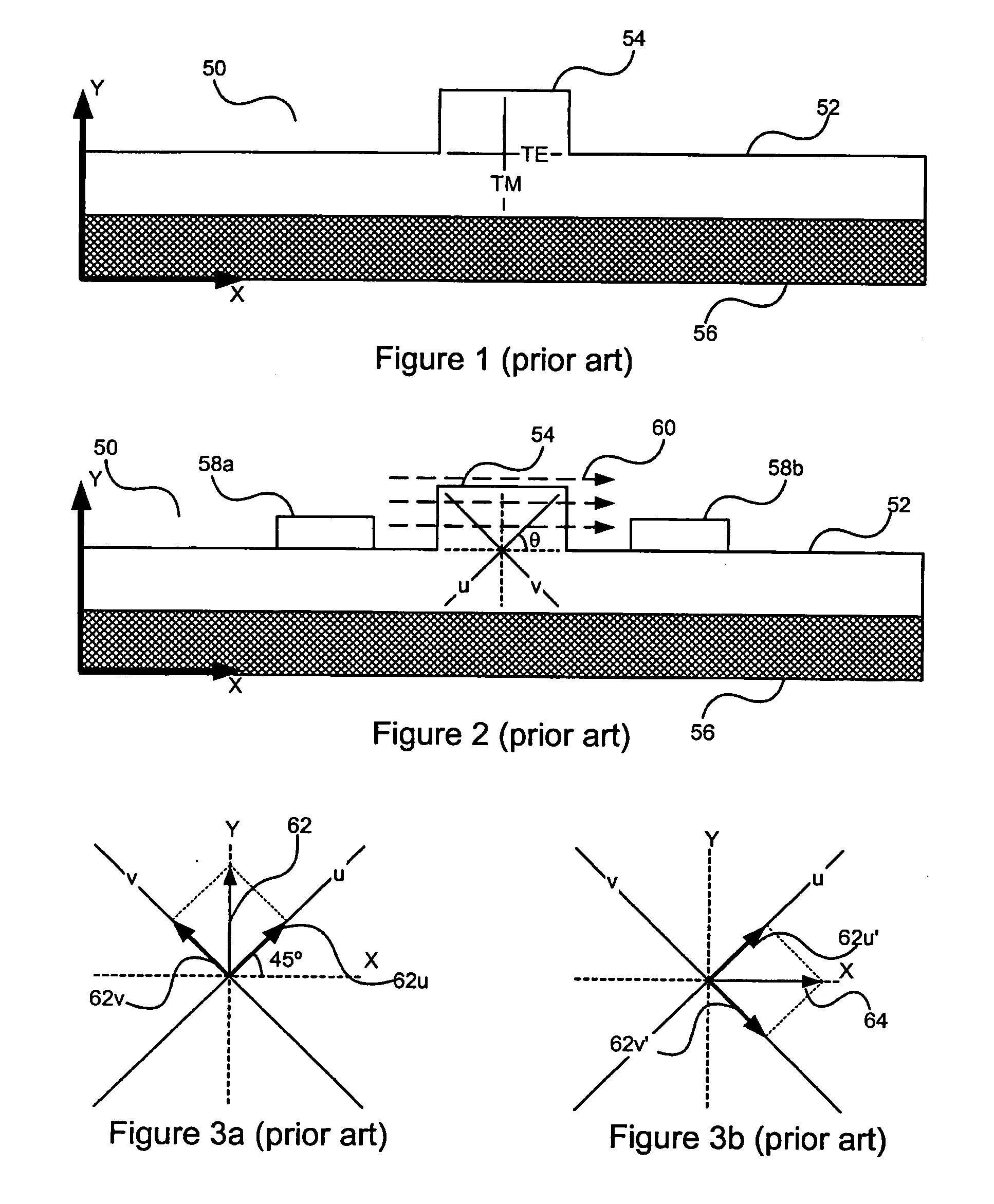
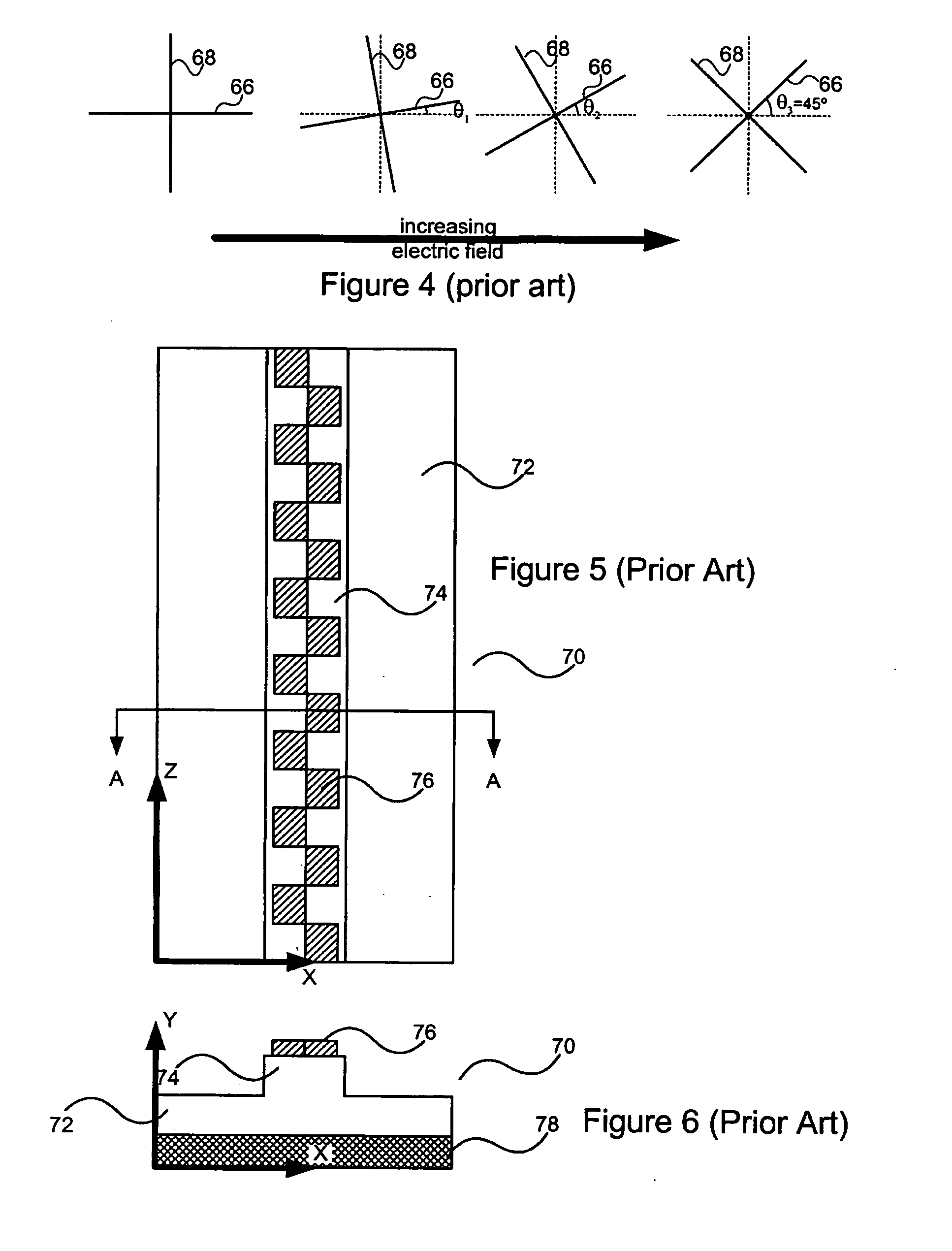
[0033] In the prior art, modulators using the electro-optic effect and polarization mode converters using inherent birefringence and passive axis rotation are taught. The use of the electro-optical effect on the prior art passive mode converters is not always feasible due to the lack of electro-optic materials in their use. Furthermore, the partial rotation of the waveguide axes in the periodic mode converters does not provide efficient electro-optic modulation.

[0034] In an ideal active mode converter, the principal axes are oriented at 45° from the TE and the TM axes and the birefringence in the principal axes is modulated by varying the electric field. This can be accomplished in three ways. The first is by having zero birefringence at zero electric field. In this configuration, the axes are undefined in the absence of birefringence and the polarization state of light entering the waveguide will be the same as light exiting the waveguide. When an electric field is applied, the de...


PUM


Abstract

A waveguide for use in polarization mode converters and polarization modulators using extrinsic strain to prerotate the principal axes and control birefringence is disclosed herein. The invention relates to the orienting of principal propagation axes in an optical waveguide by pre-stressing the waveguide, using an extrinsic stress, to re-orient the principal propagation axes from an unstressed orientation to a substantially ideal orientation. The waveguide is preferably stressed by an extrinsic strain inducer which applies a shear force to the waveguide to induce anisometry in the waveguide structure.

Description

FIELD OF THE INVENTION [0001] The present invention relates generally to mode conversion inducing optical waveguides. More particularly, the present invention relates to waveguides intentionally stressed to assist in inducing mode conversion. BACKGROUND OF THE INVENTION [0002] In the fields of integrated optical devices and electro-optical devices, polarization mode converters are known. These converters receive light polarized in a first mode and provide light at an output in a second polarization mode. [0003] Mode converters can be either active or passive. An example of an active mode converter is U.S. Pat. No. 5,566,257 to Jaeger et al, which is incorporated herein by reference. The device of the '257 patent makes use of the electro-optical effect to induce polarization mode conversion. [0004]FIG. 1 illustrates a conventional semiconductor optical waveguide 50 using a compound semiconductor 52, such as gallium arsenide (GaAs). The semiconductor layer 52 has an optical ridge 54 t...

Claims


Application Information

Patent Timeline
Patent Type & Authority Applications(United States)
IPC IPC(8): G02B6/10
CPCG02B6/126
Inventor BULL, JEFFREY D.JAEGER, NICOLAS AUGUST FLEMINGKATO, HIROSHISENIUK, DAVID ROLLAND BLAINE
Owner OPTELIAN ACCESS NETWORKS
Why Eureka
Try Eureka