Passive optical network of bus structure

a bus structure and optical network technology, applied in the field of passive optical network, can solve the problem that the pon cannot efficiently provide communication services to each subscriber without requiring a significant amount in installation costs, and achieve the effect of safe and economical provision of optical communication services and reducing population density

Inactive Publication Date: 2006-03-30
SAMSUNG ELECTRONICS CO LTD
View PDF3 Cites 26 Cited by
  • Summary
  • Abstract
  • Description
  • Claims
  • Application Information

AI Technical Summary

Benefits of technology

[0013] Accordingly, the present invention has been made to solve the above-mentioned problems occurring in the prior art, and an object of the present invention is to provi...

Problems solved by technology

However, in an area having a relatively low density of population, the RN becomes distant from each subscriber, so the conventiona...

Method used


Image

  • Passive optical network of bus structure
  • Passive optical network of bus structure
  • Passive optical network of bus structure

Examples


first embodiment

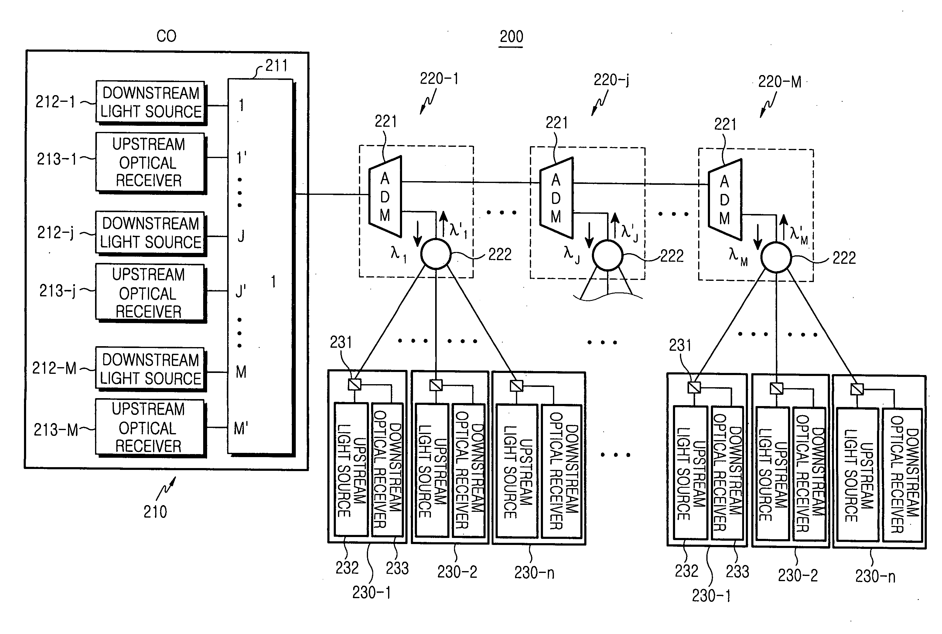
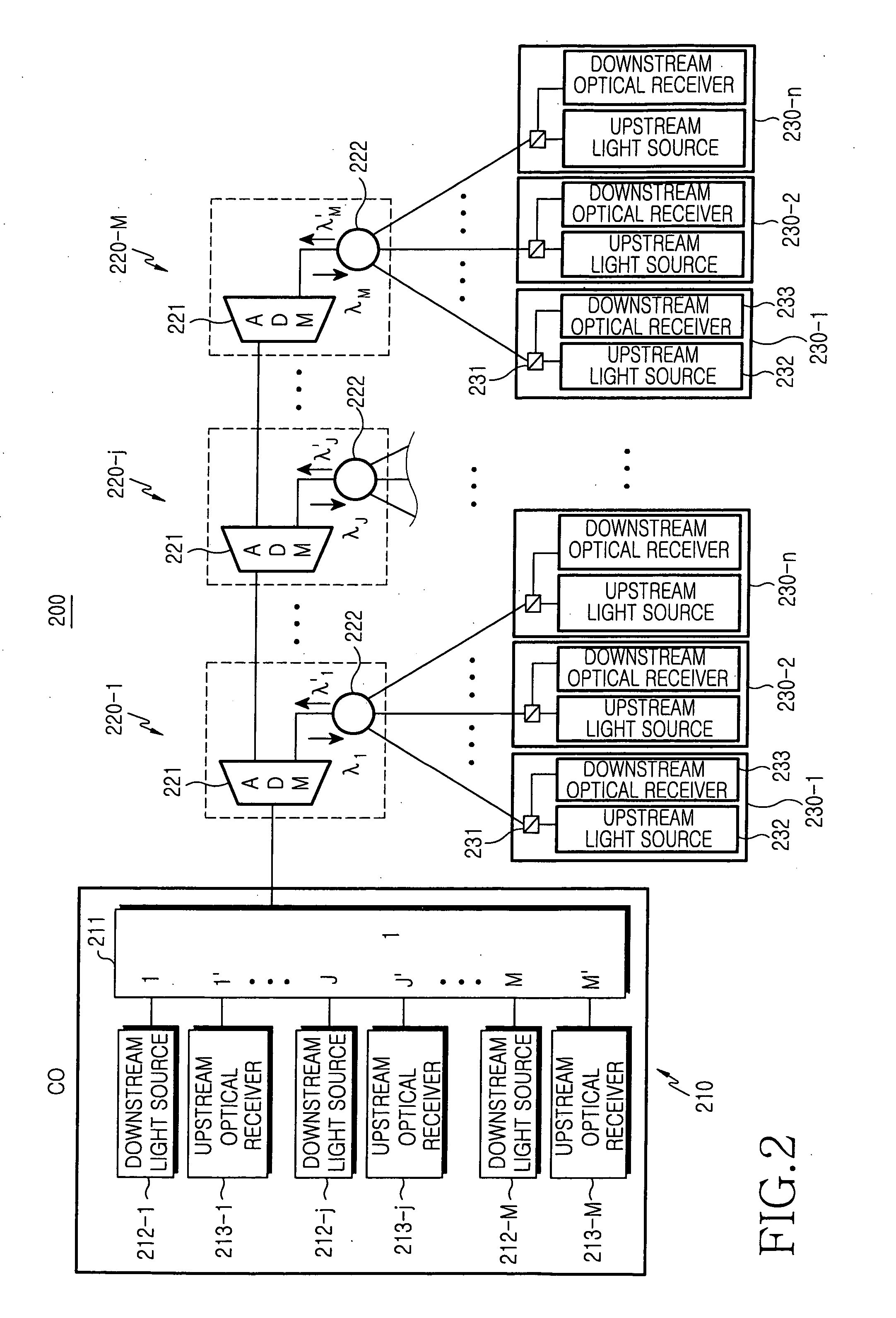
[0024]FIG. 2 illustrates a passive optical network 200 having a bus-type structure according to the present invention. The passive optical network 200 includes a central office (CO) 210 for generating time-division multiplexed and wavelength-division multiplexed downstream optical signals (λ1 . . . λM), a plurality remote nodes (RNs) 220-1 to 220-M positioned in series on the optical path linked to the CO 210 for splitting corresponding downstream optical signals, and a plurality of optical network units (ONUs) 230-1 to 230-n which are linked with a corresponding one of RNs 220-1 to 220-M. That is, the CO 210 transmits time-division multiplexed and wavelength-division multiplexed downstream optical signals to each of the RNs 220-1 to 220-M. Each of the RNs 220-1 to 220-M splits a downstream optical signal with a corresponding wavelength into a plurality of downstream channels and transmits the downstream channels to the corresponding ONUs 230-1 to 230-n linked with the corresponding...

second embodiment

[0036]FIG. 6 illustrates only an add / drop multiplexer 321-j included in the j-th remote node 320-j of the remote nodes 320-1 to 320-M shown in FIG. 5. The corresponding add / drop multiplexer 321-j extracts a downstream optical signal with a corresponding wavelength (λj) and outputs a corresponding upstream optical signal (λj′) to the CO 310. As shown in FIG. 6, the add / drop multiplexer 321 according to the present invention can extract or add a downstream optical signal and an upstream optical signal with mutually different wavelengths by employing an add / drop filter capable of reflecting the wavelengths through two ports of the add / drop multiplexer 321.

[0037] Each of the downstream optical splitters 322 splits a downstream optical signal with a corresponding wavelength (λ1 . . . λM) into a plurality of downstream channels and transmits the downstream channels to corresponding ONUs 330-1 to 330-n from among a plurality of linked ONUs. Each of the upstream optical splitters 323 time-d...


PUM


Abstract

Disclosed is a passive optical network of a bus structure. The passive optical network comprises a central office for wavelength-division multiplexing a plurality of time-division multiplexed downstream optical signals with mutually different wavelengths and receiving upstream optical signals, a plurality of remote nodes positioned in series on an optical path linked to the central office, and a plurality of optical network units for detecting a corresponding downstream channel and being linked with a corresponding remote node in order to transmit each upstream channel to the corresponding remote node, wherein each remote node splits a corresponding downstream optical signal into a plurality of downstream channels and transmits upstream channels to the central office by time-division multiplexing the upstream channels to an upstream optical signal.

Description

CLAIM OF PRIORITY [0001] This application claims priority to that patent application entitled “Passive Optical Network of Bus Structure,” filed in the Korean Intellectual Property Office on Sep. 24, 2004 and assigned Serial No. 2004-77248, the contents of which are incorporated herein by reference. BACKGROUND OF THE INVENTION [0002] 1. Field of the Invention [0003] The present invention relates to a passive optical network, and more particularly to a passive optical network including a plurality of remote nodes. [0004] 2. Description of the Related Art [0005] Generally, a passive optical network ensures superior security by providing a plurality of subscribers with optical signals having their own wavelengths, and easily expands communication capacity by multiplexing predetermined wavelength bands according to necessity. [0006]FIG. 1 illustrates a conventional wavelength-division multiplexed passive optical network (WDM-PON). The WDM-PON includes a central office (CO) 110 for provid...

Claims


Application Information

Patent Timeline
IPC IPC(8): H04J14/00H04B10/27H04B10/272H04B10/278H04B10/29H04B10/297H04J14/02H04J14/08H04L12/44
CPCH04J14/0226H04J14/0227H04J14/028H04J14/0252H04J14/0246H04J14/0247H04J14/025H04J14/0282H04B10/25H04B10/2581H04B10/278
Inventor PARK, SUNG-BUMOH, YUN-JEHWANG, SEONG-TAEK
Owner SAMSUNG ELECTRONICS CO LTD
Why Eureka
Try Eureka