Apparatus and method for laser scanner cleaning and protection

a technology of laser scanners and apparatuses, applied in lighting and heating apparatus, instruments, heating types, etc., can solve the problems of reducing the sensitivity of the device, triggering the detection of a device fault, and reducing the cost of the device, so as to reduce the surface contamination of the viewing window

Inactive Publication Date: 2006-03-30
SCI TECH INC
View PDF7 Cites 26 Cited by
  • Summary
  • Abstract
  • Description
  • Claims
  • Application Information

AI Technical Summary

Benefits of technology

[0007] The present invention comprises a method and apparatus to reduce the surface contamination of a viewing window of an optoelectronic presence sensing device, such as the “scanning” window of a laser scanner as might be used in hazardous machine guarding applications or in object avoidance system applications. More particular, the present invention uses an air guard that is supplied with a source of pressurized air to vent air toward the viewing window to reduce the surface contamination thereof. The air guard may be configured such that it blows air across or in front of the window such that airborne contaminates generally are prevented from settling on the window. Additionally, or alternatively, the air guard may be configured such that it blows more focused and / or higher velocity air streams toward the viewing window toward the window surface to remove contaminants from the window's exterior surface. More generally, the air guard can be configured to direct air toward or across the window's surface in modulated (time varying) patterns and amplitudes as needed or desired.

Problems solved by technology

Understandably, the operation of such devices can be compromised by the buildup of dust or other contamination on any device surfaces through which outgoing or reflected optical signals must pass.
For example, a given device typically uses one or more optically transparent “viewing” windows through which its optical signals are passed and any contamination of these windows can reduce device sensitivity and / or trigger the detection of a device fault.
Device faults can be costly because one or more production machines typically are tied in with a given presence sensing system, and these machines typically are automatically taken offline for the duration of any presence sensing fault condition.
As such, the buildup of contamination on the viewing windows of optoelectronic presence sensing devices raises a number of safety and efficiency issues in the typical manufacturing environment.

Method used


Image

  • Apparatus and method for laser scanner cleaning and protection
  • Apparatus and method for laser scanner cleaning and protection
  • Apparatus and method for laser scanner cleaning and protection

Examples


Embodiment Construction

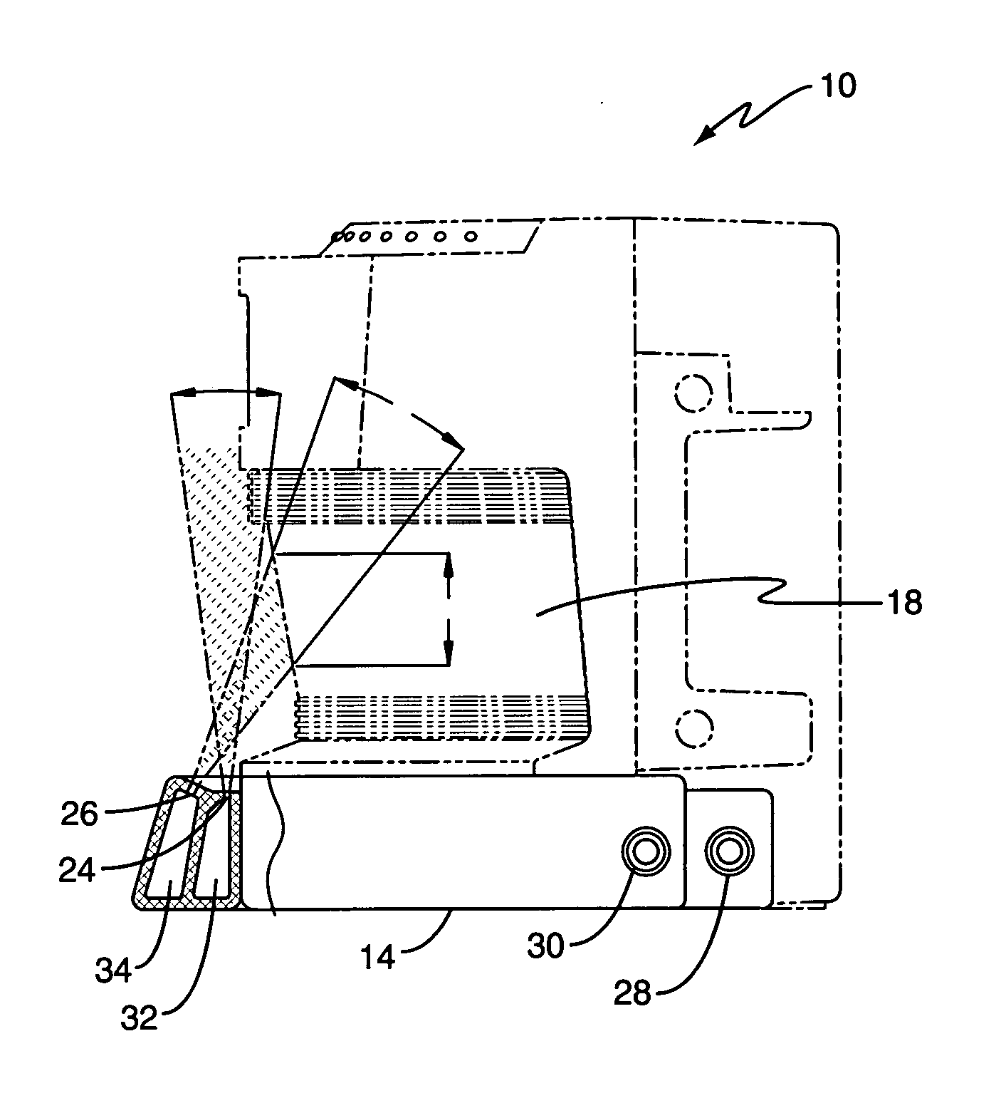
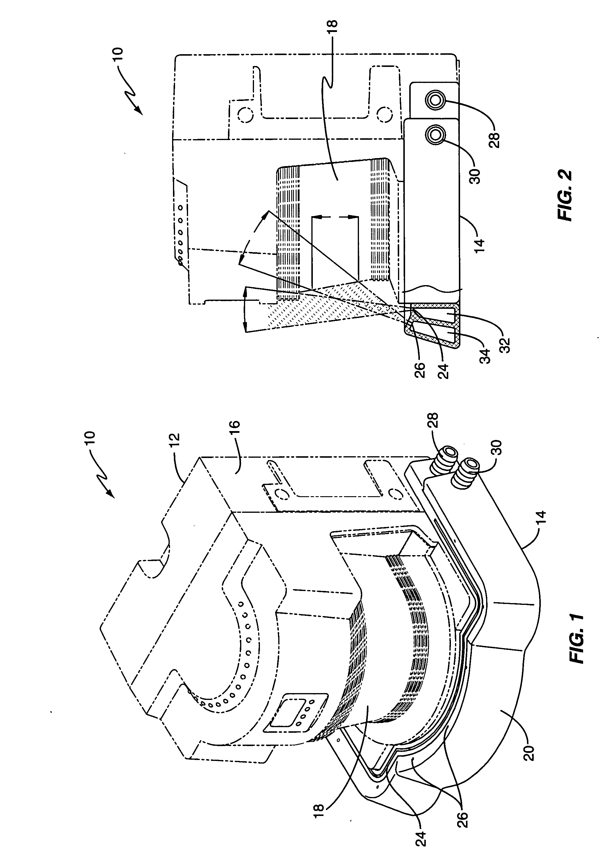
[0025]FIG. 1 is a diagram of an exemplary optoelectronic presence sensing system 10 that is configured according to one or more embodiments of the present invention. In the illustrated embodiment, system 10 comprises an optoelectronic presence sensing unit or device 12 and an associated air guard unit 14 that is integrated with or affixed to a housing 16 of the presence sensing device 12.

[0026] In operation, the air guard 14 prevents the deposition of airborne contaminants (dust, oil, etc.) on an exterior surface of a viewing window 18 of the presence sensing device 12 by creating a laminar air flow in front of window 18 and / or cleans the exterior of window 18 by directing one or more streams of air at the window 18. By preventing contamination of window18 and / or by at least partially removing surface contaminants from window 18, air guard 14 improves the operation of presence sensing device 10. That is, use of air guard 18 can reduce the frequency at which maintenance personal mus...


PUM


Abstract

An air guard directs air toward a viewing window of an optoelectronic presence sensing device to reduce surface contamination thereon. The air guard may include a control valve, and possibly control circuits, to enable selective activation of the air guard. In one embodiment, the air guard includes one or more slits configured to vent pressurized air in a generally laminar (curtain like) flow in front of the window to prevent the deposition of airborne contaminants thereon. Alternatively, or additionally, the air guard may include one or more nozzles configured to vent pressurized air in directed air streams toward the window to remove surface contaminants thereon, and may include a control valve enabling selective operation in preventive, cleaning, or standby modes. Mode control may be effected by an external control system, by the presence sensing device, or by the air guard itself, which may include a timer or other control circuit.

Description

BACKGROUND OF THE INVENTION [0001] The present invention generally relates to optoelectronic presence sensing devices, and particularly relates to the use of forced air systems to facilitate the maintenance and operation of such devices. [0002] Optoelectronic presence sensing devices find wide use in a variety of industrial applications. For example, one prevalent use arises in the context of “machine guarding,” wherein the object detection functionality of such presence sensing systems provides a triggering mechanism for shutting down hazardous machines before personnel get too close. Because of the safety-critical nature of this type of application, the installation, testing, and ongoing maintenance of such presence sensing systems represent vital functions. [0003] Other critical uses of such presence sensing systems include vehicle navigation and / or collision avoidance systems. For example, a shop floor forklift or other utility vehicle may be configured with one or more optical ...

Claims


Application Information

Patent Timeline
Patent Type & Authority Applications(United States)
IPC IPC(8): F24F9/00
CPCG08B29/22G08B13/18
Inventor ASHFORD, JAMES A.LAZZARA, JOSEPH J.
Owner SCI TECH INC
Why Eureka
Try Eureka