
Wireless communication mapping apparatus, systems, and methods

a mapping apparatus and wireless communication technology, applied in the field of communication, can solve problems such as distorted audio, dropped calls, and distorted audio

Inactive Publication Date: 2006-03-30
INTEL CORP
View PDF8 Cites 15 Cited by
  • Summary
  • Abstract
  • Description
  • Claims
  • Application Information

AI Technical Summary

Problems solved by technology

Wireless communications systems, including packet-switched radio-frequency (RF) technologies, may be subject to various signal-degrading conditions associated with RF transmission and reception.
Weak signals, electromagnetic interference, phase shifts, summation / cancellation of signals, and inter-channeU inter-cell interference may result in dropped calls, distorted audio, and slow data connections.

Method used


Image

  • Wireless communication mapping apparatus, systems, and methods
  • Wireless communication mapping apparatus, systems, and methods
  • Wireless communication mapping apparatus, systems, and methods

Examples


Embodiment Construction

[0006] Various embodiments disclosed herein may be applied to improve awareness of service quality that may exist at different geographical points within a wireless communications system service area. In some embodiments, poor communication conditions may be improved via inter-system feedback.

[0007] Congestion, RF signal conditions, and other systemic factors may vary temporally and / or geographically within a system coverage area, and may greatly affect service quality. Some embodiments disclosed herein may collect these factors (e.g., in the form of data points), and organize them into a real-time, dynamically updated map that can inform users and the system itself of geographically-related signal conditions. Further, the acquired data may be used to make real-time system parametric adjustments, possibly improving system resource effectiveness.

[0008] For example, a wireless system may collect a signal-to-noise-ratio (SNR) reported by each currently-active client, and respond by a...


PUM


Abstract

Apparatus and systems, as well as methods and articles, may operate to generate a system coverage map from a plurality of geosystemic data points, as well as to change wireless system operational parameters responsive to various parameters associated with the plurality of geosystemic data points.

Description

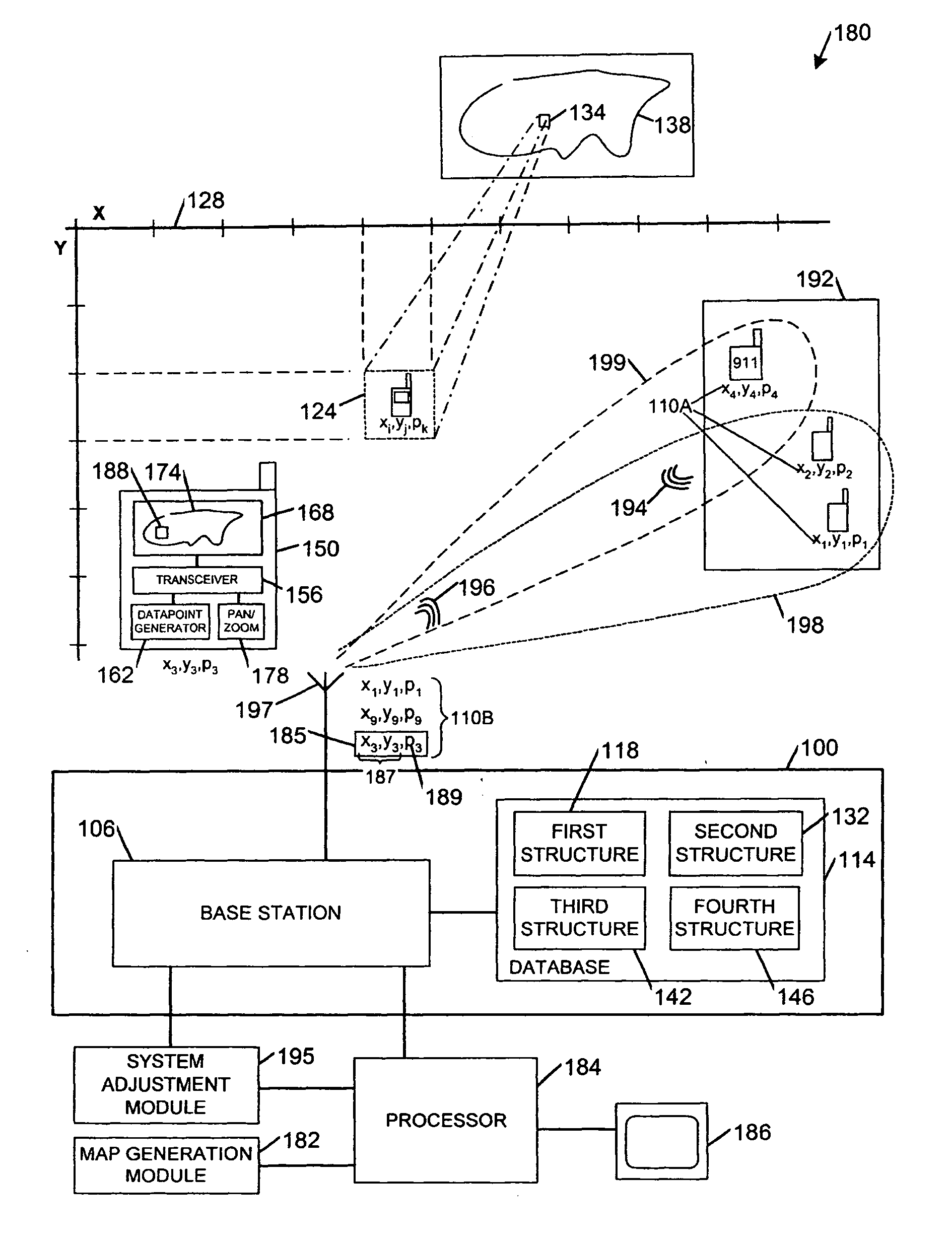
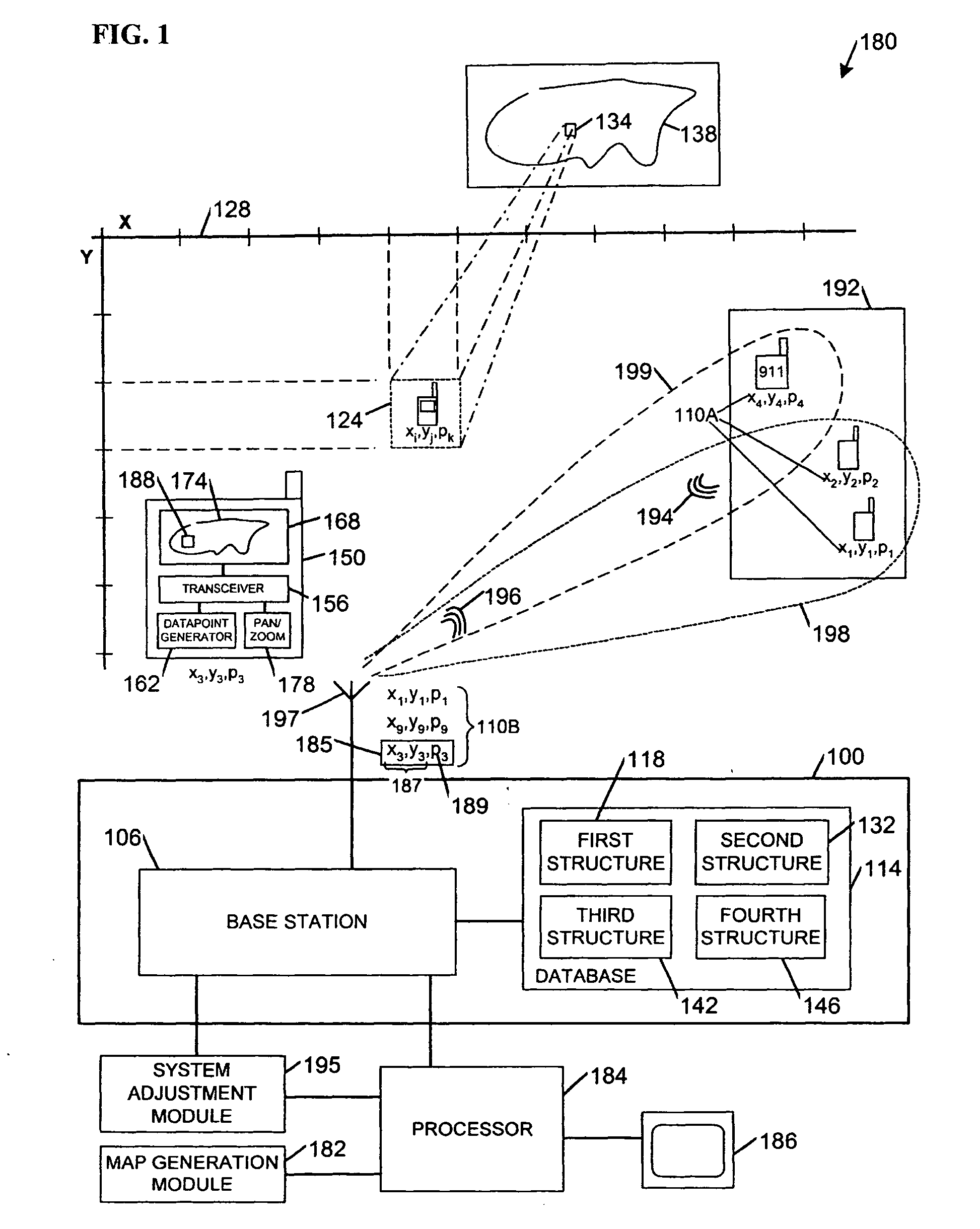
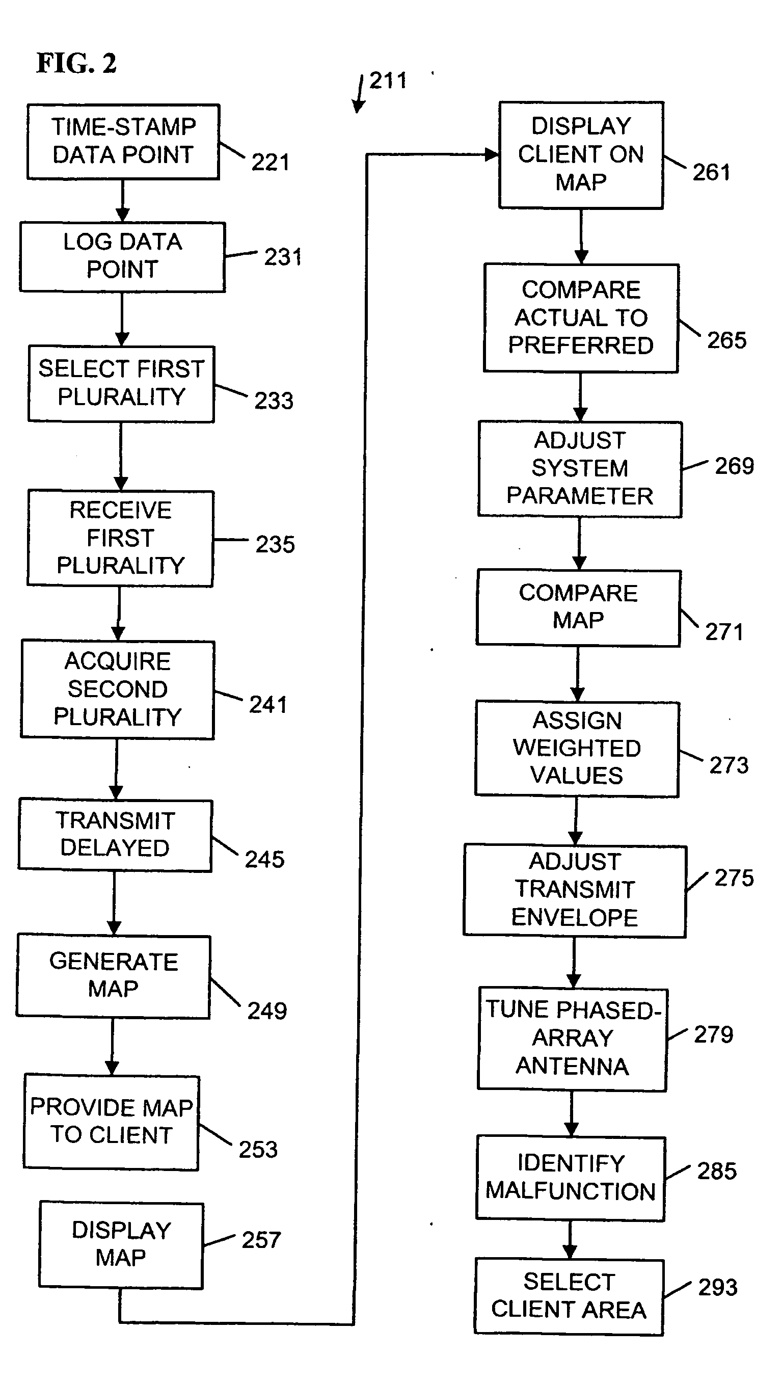
TECHNICAL FIELD [0001] Various embodiments described herein relate to communications generally, including apparatus, systems, and methods used to transmit and receive information via wireless networks. BACKGROUND INFORMATION [0002] Wireless communications systems, including packet-switched radio-frequency (RF) technologies, may be subject to various signal-degrading conditions associated with RF transmission and reception. Weak signals, electromagnetic interference, phase shifts, summation / cancellation of signals, and inter-channeU inter-cell interference may result in dropped calls, distorted audio, and slow data connections. The affected user, operating at the mercy of a poorly-responding system, may only be aware of the result, and not the condition(s) causing it.BRIEF DESCRIPTION OF THE DRAWINGS [0003]FIG. 1 is a block diagram of an apparatus and a system according to various embodiments of the invention. [0004]FIG. 2 is a flow diagram illustrating several methods according to v...

Claims


Application Information

Patent Timeline
IPC IPC(8): G06F7/00H04W16/18
CPCH04W16/18G01S5/0027
Inventor RHEMTULLA, AMIN F.LAM, SIU H.MIAO, KAI X.
Owner INTEL CORP
Learn More