
Using power of a pilot channel to control output power from a transmitter

Active Publication Date: 2006-03-30
WSOU INVESTMENTS LLC
View PDF9 Cites 10 Cited by
  • Summary
  • Abstract
  • Description
  • Claims
  • Application Information

AI Technical Summary

Benefits of technology

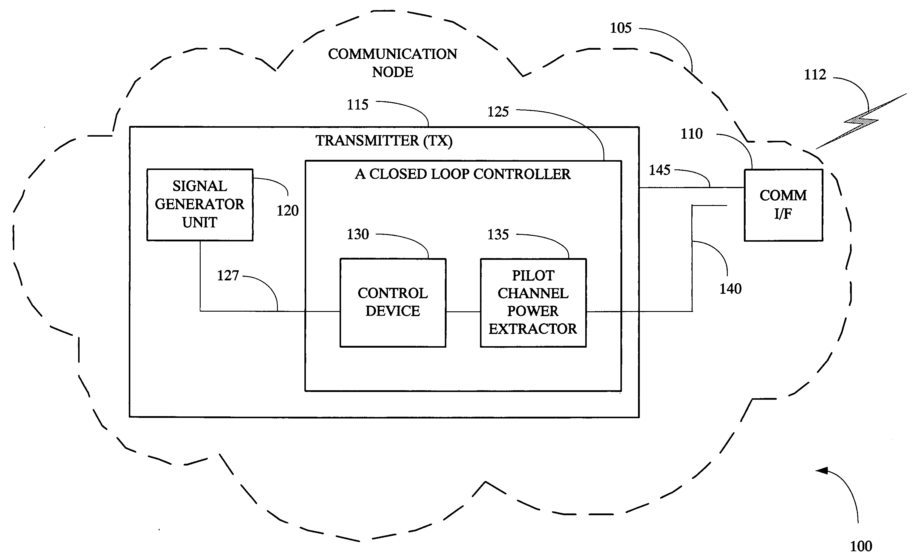
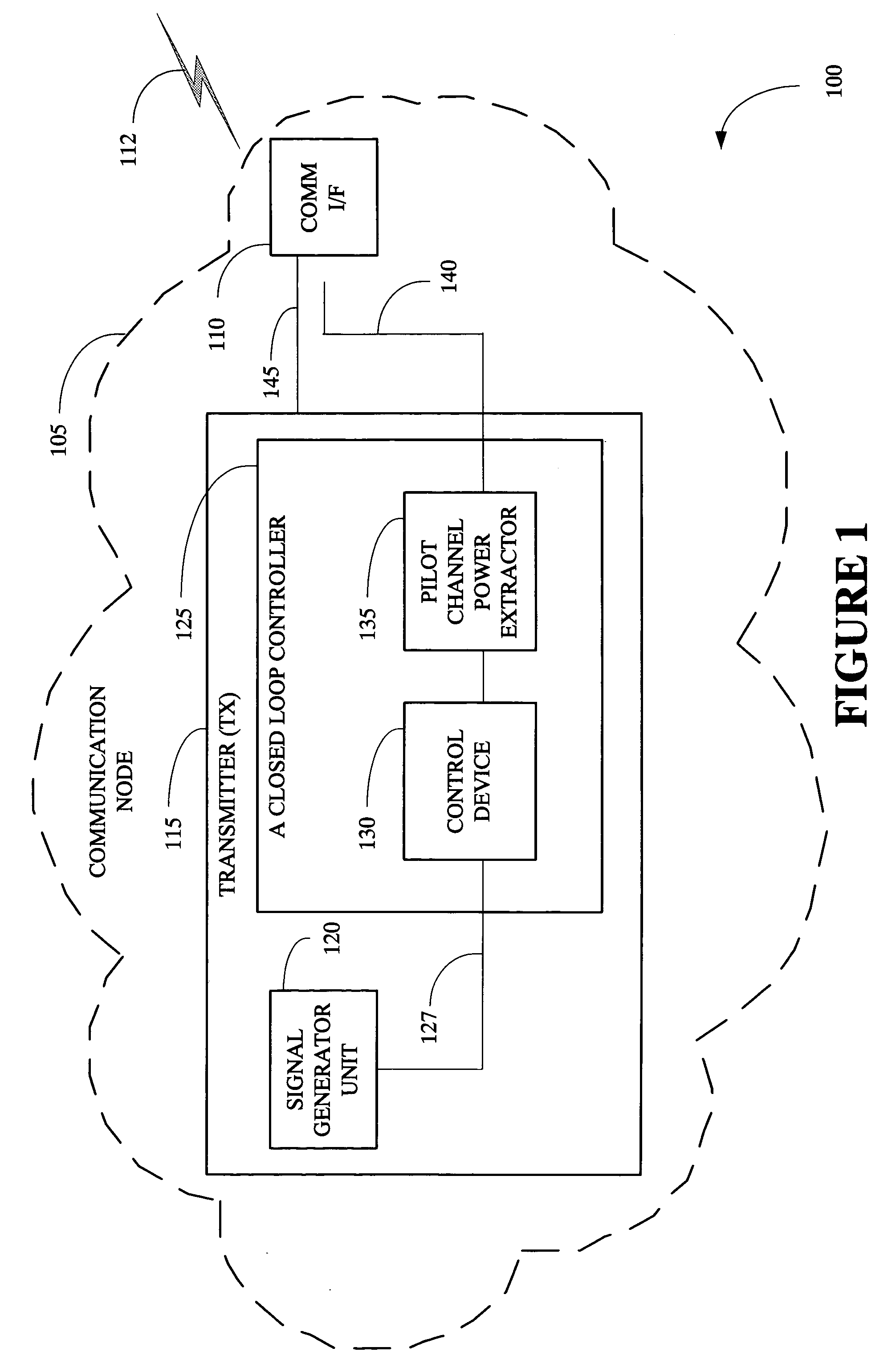
[0010] In one embodiment of the present invention, a method is provided for controlling an output power from a transmitter associated with a communication node in a wireless network. The method comprises extracting an indication of a pilot channel power from a portion of an output signal of the transmitter and controlling a control loop having one or more control devices in said transmitter based on the indication of a pilot channel power such that the pilot channel power stays substantially constant over a period of time.
[0011] In another embodiment, a transmitter associated with a communication node in a wireless network to communicate with a mobile device. The transmitter may comprise an extractor to derive an indication of a pilot channel power from a portion of an output signal of the transmitter and a control device coupled to the extractor. The control device may control a control loop in the transmitter based on the indication of a pilot channel power such that the pilot channel power stays substantially constant over a period of time.
[0012] In yet another embodiment, a digital cellular network may comprise a plurality of cells to communicate with a mobile device over a wireless medium, wherein at least one of the plurality of cells ma

Problems solved by technology

However, increasing system capacity to meet this increased demand while maintaining a quality of services to users of mobile communications systems with a limited number of radio channels presents a constant challenge.
So the actual and the average output power no longer is an accurate measure for the power setting needed to cover a certain cell size.
However, the comparison must be done using the same absolute time intervals for the input and output signals, providing a relatively imprecise control of a cell size while using a substantially large number of measurement components in the gain control loop.
One disadvantage of this technique is that every transmitter stage inside the gain control loop adds delay to the output signal.
Thus, may additional delay element may be needed.
The second disadvantage is the fact that a constant gain per se does not indicate a constant output signal behavior.
The third disadvantage is the fact that the gain control loop only keeps one of the four transmission parameters constant.
Any imperfection in the uncontrolled S-parameter values typically leads to an uncontrolled signal variation on the output signal.

Method used


Image

  • Using power of a pilot channel to control output power from a transmitter
  • Using power of a pilot channel to control output power from a transmitter
  • Using power of a pilot channel to control output power from a transmitter

Examples


Embodiment Construction

[0022] Illustrative embodiments of the invention are described below. In the interest of clarity, not all features of an actual implementation are described in this specification. It will of course be appreciated that in the development of any such actual embodiment, numerous implementation-specific decisions may be made to achieve the developers' specific goals, such as compliance with system-related and business-related constraints, which may vary from one implementation to another. Moreover, it will be appreciated that such a development effort might be complex and time-consuming, but would nevertheless be a routine undertaking for those of ordinary skill in the art having the benefit of this disclosure.

[0023] Generally, a method of using a channel power of a pilot channel to control the output power from a transmitter, such as a base transceiver station (BTS) transmitting spread spectrum signals to mobile devices is provided. By analyzing the content of a transmitter output sig...


PUM


Abstract

The present invention provides a method and an apparatus for using power of a pilot channel to control an output power from a transmitter, such as a base station transmitting spread spectrum signals. In one embodiment, a method for controlling an output power from a transmitter associated with a communication node (e.g., Node B) in a wireless network, such as a digital cellular network is provided. The method comprises extracting an indication of a pilot channel power from a portion of an output signal of the transmitter and controlling a control loop having one or more control devices in the transmitter based on the indication of a pilot channel power such that the pilot channel power stays substantially constant over a period of time. In this manner, using a closed power loop controller, a transmitter may overcome the problem of measuring the power of a non-constant spread spectrum signal and a traffic independent measure may control a cell size. Compared to a gain control loop, a relatively more precise control of the cell size may be provided using a significantly less measurement components.

Description

BACKGROUND OF THE INVENTION [0001] 1. Field of the Invention [0002] This invention relates generally to telecommunications, and more particularly, to wireless communications. [0003] 2. Description of the Related Art [0004] Advances in wireless technology have transformed mobile communications, leading to widespread acceptance and use of cellular technology. However, increasing system capacity to meet this increased demand while maintaining a quality of services to users of mobile communications systems with a limited number of radio channels presents a constant challenge. To support a range of voice and data communications, as well as video, in mobile communication systems, a geographic service area may be partitioned into a number of cells. Each cell has a cell site (also called a base station) connected to a wireline network. The cell site establishes a wireless link over radio channels with wireless communication devices, such as mobile devices within the cell. The mobile device ...

Claims


Application Information

Patent Timeline
IPC IPC(8): H04Q7/20H04W52/16H04W52/34H04W52/52
CPCH04W52/16H04W52/52H04W52/34
Inventor ECKL, WOLFGANG FRANZ
Owner WSOU INVESTMENTS LLC
Learn More