Spread spectrum transceiver for use in wireless local area network and having multipath mitigation

a spectrum transceiver and wireless local area network technology, applied in wireless communication, phase-modulated carrier systems, baseband system details, etc., can solve the problems of not being the algorithm using an snr to obtain the highest signal is not the best, and the signal may not be the best signal element, etc., to achieve good diversity selection metric, improve diversity scheme performance, and increase the effect of energy

Inactive Publication Date: 2003-08-05
INTELLECTUAL VENTURES I LLC +1
View PDF32 Cites 133 Cited by
  • Summary
  • Abstract
  • Description
  • Claims
  • Application Information

AI Technical Summary

Benefits of technology

Antenna diversity is important to go about deciding which is the best antenna, such as when two antennae are situated in a circuit board. It has been known that it is possible to demodulate the data off two antennas that are typically positioned on a circuit board, such as well known to those skilled in the art. The circuits of a spread spectrum transceiver would then determine which antenna came out with the "cleaner" set of data. However, in many prior art systems, this would require two receivers. Thus, it is necessary to obtain a good diversity selection metric.
Typically, a laptop computer used in a WLAN configuration would have two antennas that are formed as rubber coated antennas, as known to those skilled in the art. These antennae could stick out from the board. There have been various designs for antenna diversity, such as antennas that pull out and turn to the side, or that permanently stick out. With two antennas, it is necessary to determine what antenna to pick. One known way is to use the signal-to-noise ratio (SNR) to pick the required antenna.
However, in a large office environment with many doors and walls, the environment is similar to an echo chamber. The signal that is best for the receiver may not be the largest signal and this largest signal may not be the best signal element in terms of demodulating the signal. All signs could be corrupted by multipath. Thus, the signals subtract and could make a signal weaker and a previous algorithm using the SNR would be appropriate. However, if the multipath made a more powerful, corrupted signal, then the algorithm using an SNR to obtain the highest signal would not be the best. The actual demodulated signal would be a more corrupted signal, even though it had greater energy.
It is desirable to find the least corrupt signal, and not the highest power signal. The present invention uses a correlation technique to decide what is the best, least corrupt signal to demodulate, instead of looking only at the greatest power signal as in prior art techniques.
Basically, the system looks to the left and right of reference and does a subtraction to obtain the cleaner signal. It is a diversity scheme to determine which of two antennas are better for receiving the next signal. It could also be accomplished for transmitting the next signal because if reception is good, then the path back is generally also good, although that is not always guaranteed. The metric gives an advantage to multipath corrupt environments.
As to measurements, they have been accomplished on Barker codes. It is possible to make a decision whether a Walsh or other similar signal is good not based solely on the Barker codes. It is possible to use an additional second antenna diversity period to refine an estimate of what is the better signal. Thus, it is possible to improve the performance of the diversity scheme.

Problems solved by technology

The high rate modulation is more susceptible to multipath interference and filter distortion than lower rate modulations would be due to the higher required SNR.
However, in many prior art systems, this would require two receivers.
The signal that is best for the receiver may not be the largest signal and this largest signal may not be the best signal element in terms of demodulating the signal.
However, if the multipath made a more powerful, corrupted signal, then the algorithm using an SNR to obtain the highest signal would not be the best.
Antenna diversity also reduces the probability of "dead spots," which are very annoying to users.
This low end receiver will lose significant throughput with larger delay spreads.
However, the diversity scheme works with higher delay spreads to choose the low delay spread antenna, if one is available.
Not subtracting the sample the predetermined number of chips early results in only a small performance loss.
Multipath as described above is a recurring problem in spread spectrum communications, especially with the use of WLAN systems.
One problem in an aspect of the technology is that there are two portions of one type of waveform: (1) the preamble portion, and (2) the longer data portion.
A problem with multipath distortion is that the chips coming into the correlator are distorted by the multipath (the echoes) coming into the receiver.
The compensation techniques can greatly increase complexity.
The filters cause multiple-chip-duration distortion.
This causes a significant smearing of the channel fingers.
The Barker word is limited in its ability to estimate channel impulse response this long.
The receiver complexity is driven by this effect.
Thermal noise is another important issue.
An important issue is evaluating to what degree noise is important versus multipath effects.
Some designs may be more noise robust but less multipath robust.
An issue arises concerning the importance of weighting for performance in real-world situations.
However, it is believed that the narrowband-equalized signaling has not been previously analyzed sufficiently to uncover strong merits in its favor.
Unfortunately, the present situation is complicated by other factors.
Multipath is a major performance limiting impairment along with the AWGN.
These additional factors lead to an erosion of the normal "rules of thumb" known to those skilled in the art.
The signals which conserve TX power by operating at low Eb / No's must necessarily consume bandwidth.
The narrowband band-capacity-optimization approach is preferred primarily because it is more difficult to maximize band-capacity by coordinating users in the wideband approach.
The CDMA springing in the 802.11 bands is too low to provide adequate processing gain.
Adaptive power control needed to realize multiple access is difficult.
The WLAN systems tend to be more uncoordinated than the Cellular / PCS systems for reasons that are apparent to the those skilled in the art.
The section on capacity loss through waveform features overhead describes that certain proposed waveforms carry bandwidth consuming, data-rate limiting features which tend to limit capacity performance.
This intersymbol interference (ISI) can be significant, requiring equalization to mitigate the performance loss.
Unfortunately, the multipath spread is very long compared to practical RAKE symbol durations.
Hence, under non-trivial multipath spreads, the 802.11 proposed RAKE techniques suffer significant loss from ISI.
The drawback is the design of symbols with good correlation properties consumes bandwidth as shown in FIG. 22.
This limits the capacity of the single user, thereby limiting multi-user capacity within a band.
Another situation arises which greatly weakens the use of signals with good autocorrelation properties.
However, by attempting to load many information bits upon the 11-bit Barker word, overall good properties are lost.
In addition, the distortion of multipath becomes problematic.
The convenience of an impulsive autocorrelation kernel is largely lost.
This complexity is so high, sub-optimal short-cuts must be made.
Most of the proposals presented are fundamentally limited in data.
One issue is, "Is the chip level SNR sufficiently high to allow chip-level processing, or is the processing gain of the many-chip symbol needed to realize adequate performance?"
This data packing results from trying to force many data bits through a limited bandwidth.

Method used


Image

  • Spread spectrum transceiver for use in wireless local area network and having multipath mitigation
  • Spread spectrum transceiver for use in wireless local area network and having multipath mitigation
  • Spread spectrum transceiver for use in wireless local area network and having multipath mitigation

Examples


Embodiment Construction

of FIG. 31 requires FF weight calculation before the FB weights can be computed. Using the zero-forcing (ZF) criterion, two FF weights can be solved using the matrix shown in FIG. 32. Once the channel impulse response is known, the coefficient matrix is known. Simple inversion gives the result. The two FF weights and the w.sub.1 and w.sub.0 solution is simply h.sub.1 and h.sub.0 scaled by the same complex constant. Solving for 3 FF taps is similar.

Once the FF weights have been calculated, the FB taps are derived by convolving the channel impulse response with the FF weights. The trailing taps in the output convolution become the FB taps.

To vary complexity, a designer decides how many taps are needed to obtain a desired level of performance. These options are illustrated by using only FB taps, using only 2 FF taps, and using 3 FF taps. The number of FB taps is varied in each case.

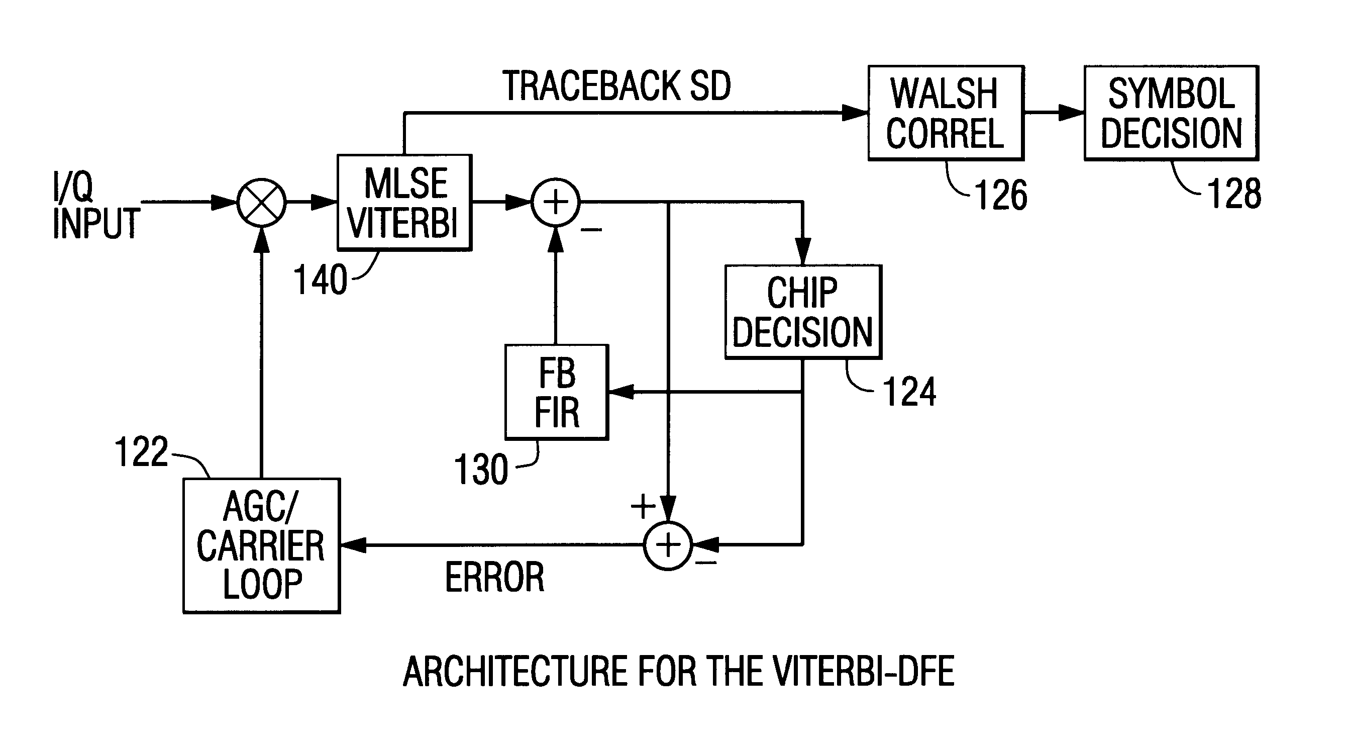
The architecture and performance for a DFE, which uses only FB taps, is shown in FIG. 33. For a QPSK sign...


PUM


Abstract

A method and spread spectrum transceiver for demodulating a spread spectrum signal is disclosed. A spread spectrum phase shift keyed (PSK) modulated information signal is received within a demodulator of a spread spectrum receiver on a signal channel. The information signal includes a sequence of data symbols formed from a plurality of high rate mode chips. A precursor portion of the signal channel is Viterbi detected. A multi-state trellis is formed having a predetermined number of states. A post-cursor portion of the signal channel is feedback equalized with a finite impulse response filter having feedback taps operatively connected to a chip detection circuit that tracks high rate mode chips and a carrier loop circuit for phase and frequency tracking. The information signal is despread within a spread spectrum code function correlator.

Description

This invention relates to the field of communication electronics, and more particularly, to a spread spectrum transceiver for use in wireless local area networks.Wireless or radio communication between separated electronic devices is widely used. For example, a wireless local area network (WLAN) is a flexible data communication system that may be an extension to, or an alternative for, a wired LAN within a building or campus. A WLAN uses radio technology to transmit and receive data over the air, thereby reducing or minimizing the need for wired connections. Accordingly, a WLAN combines data connectivity with user mobility, and, through simplified configurations, also permits a movable LAN.Over the past several years, WLANs have gained acceptance among a number users including, for example, health-care, retail, manufacturing, warehousing, and academic areas. These groups have benefitted from the productivity gains of using hand-held terminals and notebook computers, for example, to ...

Claims


Application Information

Patent Timeline
Patent Type & Authority Patents(United States)
IPC IPC(8): H04L25/03H04B7/08H04B1/707H04L12/28H04L27/227H04B1/709H04B1/711
CPCH04B1/707H04B1/711H04B7/0811H04L25/03267H04B1/709H04B7/08H04L2025/03401H04W84/12H04W88/02H04L27/18
Inventor ANDREN, CARLWEBSTER, MARK A.
Owner INTELLECTUAL VENTURES I LLC
Why Eureka
Try Eureka