Expandable needle suture apparatus and associated handle assembly with rotational suture manipulation system

a technology of suture manipulation and expandable needles, which is applied in the field of surgical suture devices, can solve the problems of needles so small they tend to yield under compressive stresses, complicated tasks, and difficult integration of all tasks into a single instrument, and achieve the effect of easy suture passing and easy loading

Active Publication Date: 2006-03-30
DEPUY SYNTHES PROD INC
View PDF26 Cites 122 Cited by
  • Summary
  • Abstract
  • Description
  • Claims
  • Application Information

AI Technical Summary

Benefits of technology

[0010] In this expanded state, the open slot can be easily loaded with a suture. The needle assembly can then be pulled into a carrier tube that compresses the two bifurcated sides of the slot to shrink the profile of the distal tip and engage the loaded suture. With its sharp tip, the needle assembly, compressed within the outer tube, can th...

Problems solved by technology

One of the more challenging aspects of endoscopy/arthroscopy is to properly place a suture in identified tissue.
This task is complicated by the fact that all work must be done through a 5-8 millimeter cannula while viewing one's efforts on a monitor.
With these difficult size configurations, it has been a significant challenge to incorporate all of the tasks into a single instrument.
As a result, the tasks for initially passing a suture through target tissue and subsequently retrie...

Method used


Image

  • Expandable needle suture apparatus and associated handle assembly with rotational suture manipulation system
  • Expandable needle suture apparatus and associated handle assembly with rotational suture manipulation system
  • Expandable needle suture apparatus and associated handle assembly with rotational suture manipulation system

Examples


Embodiment Construction

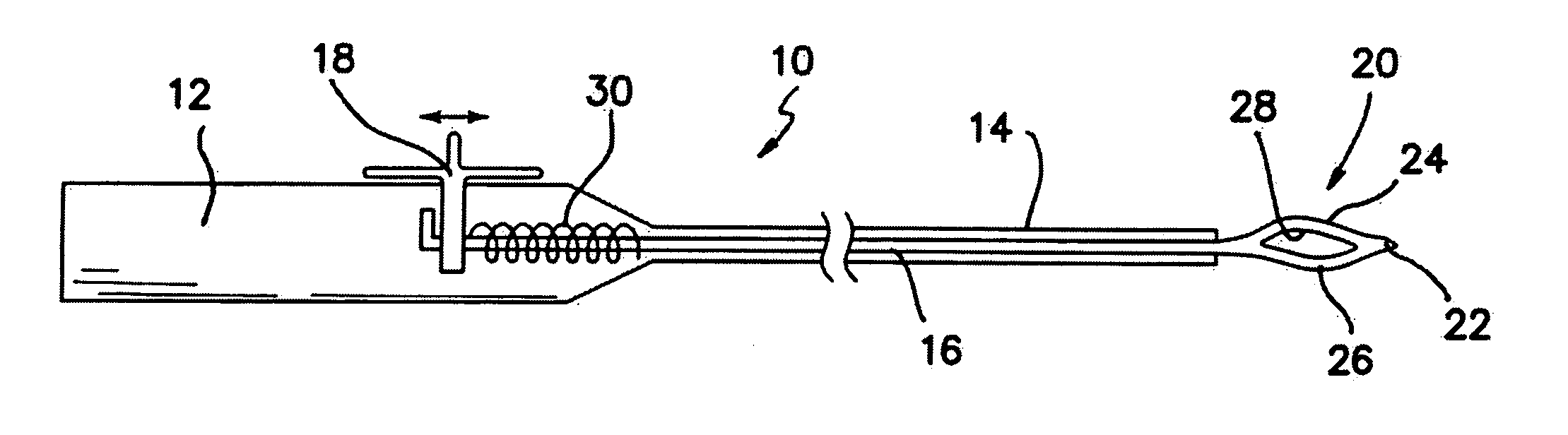
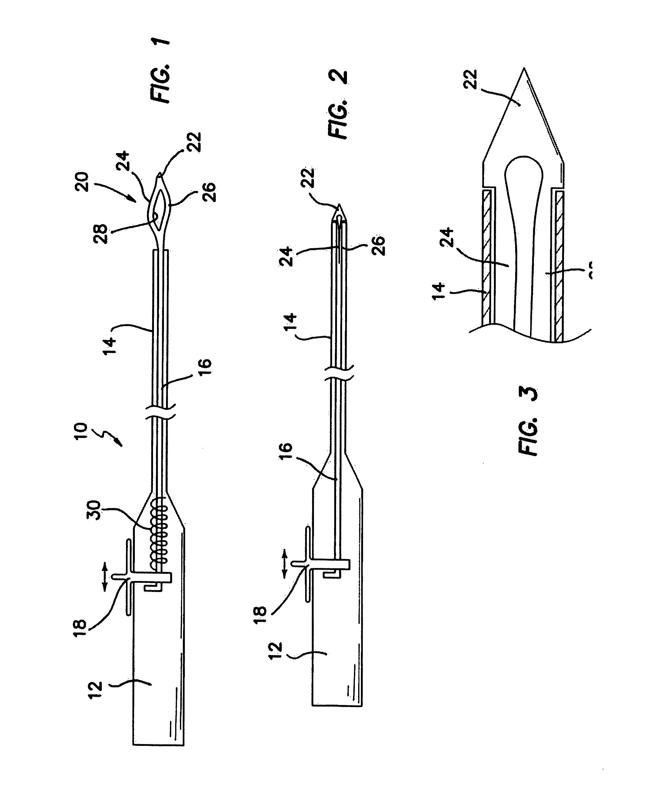
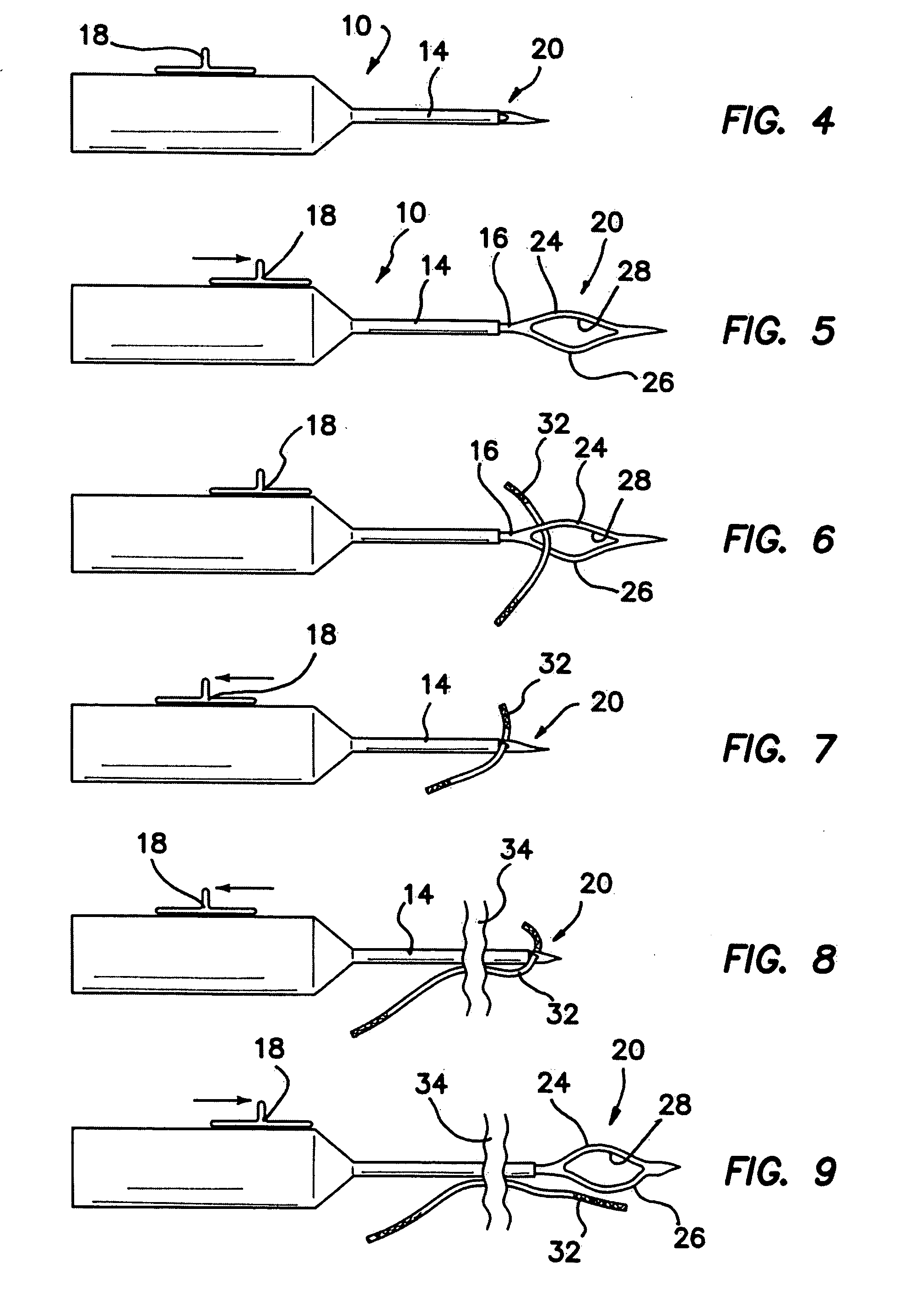
[0070] A suture device is illustrated in FIG. 1 and designated by the reference numeral 10. The device is an elongate structure and includes a handle 12 at its proximal end and a hollow shaft 14 at its distal end. An actuating rod 16 is disposed within the hollow shaft 14 and extends from the handle 12 through the shaft 14. In the handle 12, the actuating rod 16 is engaged by a thumb slide 18. At its distal end, the actuating rod 16 is coupled to a needle assembly 20. This assembly 20 includes a sharp tip 22 and bifurcated portions 24 and 26, which define a slit or slot 28 proximately of the tip 22.

[0071] Operation of the thumb slide 18 relative to the handle 12 moves the actuating rod 16 and the attached needle assembly 20 between an extended position as illustrated in FIG. 1, and a retracted position as illustrated in FIGS. 2 and 3. In this particular embodiment, a spring 30 is used to bias the rod 16 and needle assembly 20 proximally to the retracted position. It will also be no...


PUM


Abstract

A surgical suturing device (10) having an axis extending between a proximal end and a distal end is operable to move a suture (32) through body tissue (34). A handle assembly (110) is coupled to an elongated shaft (14) having a hollow configuration. An actuating rod (16) is disposed to extend between the handle assembly (110) and the shaft (14). A thumb actuation assembly is coupled to a proximal end of the actuating rod (16) for moving the rod both axially and rotationally. A needle assembly (2) at the distal end of the actuating rod (16) is movable with the actuating rod (16) between an extended state and a retracted state and at various angular orientations. Bifurcated portions (24, 26) of the needle assembly (20) define a suture slot (28), the bifurcated portions having a proximate relationship when the needle assembly (20) is in the retracted state and having a separated relationship when the needle assembly (20) is in the extended state. The needle assembly (20) is biased to the retracted state and the bifurcated portions (24, 26) are biased to the separated relationship. A handle assembly (110) is operable to move the needle assembly (20) between a free suture state and a captured suture state. In an associated method of use, the needle is bifurcated to form at least one pair of arms (24, 26 or 26b, 38b) to define a suture slot (28).

Description

CROSS REFERENCE TO RELATED APPLICATIONS [0001] This application claims the benefit of Provisional Application Ser. No. 60 / 604,243 filed on Aug. 24, 2004, and entitled, “SUTURE MANIPULATION SYSTEM WITH ROTATIONAL FINGERS,” and is a continuation-in-part of prior non-provisional application Ser. No. 10 / 803,406, filed Mar. 17, 2004, and entitled “EXPANDABLE NEEDLE SUTURE APPARATUS AND ASSOCIATED HANDLE ASSEMBLY,” now pending, which claims the benefit of Provisional Application Ser. No. 60 / 455,859 filed on Mar. 18, 2003, and entitled, “EXPANDABLE NEEDLE SUTURE APPARATUS AND METHOD,” and Provisional Application Ser. No. 60 / 500,046 filed on Sep. 3, 2003, and entitled, “EXPANDABLE NEEDLE SUTURE APPARATUS AND ASSOCIATED HANDLE ASSEMBLY,” all of which are fully incorporated herein by reference.BACKGROUND OF THE INVENTION [0002] 1. Field of the Invention [0003] This invention relates generally to surgical suture apparatus and, more specifically, to needle and suture manipulating apparatus and ...

Claims


Application Information

Patent Timeline
IPC IPC(8): A61B17/04
CPCA61B17/0483A61B17/0485A61B17/06004A61B17/06066A61B2017/0046A61B2017/0472A61B2017/06019A61B2017/06042A61B2017/2929A61B17/0469A61B2017/06009
Inventor WEISEL, THOMASPADGET, MARTIN
Owner DEPUY SYNTHES PROD INC
Why Eureka
Try Eureka