Method and computer program product for resource planning
a resource planning and computer program technology, applied in the field of resource planning, can solve the problems of difficult to optimize the configuration of the resource to be provided next, the resource that the service provider providing the hosting environment provides cannot automatically have an optimized configuration with respect to a customer's resource allocation request, and the difficulty of fully obtaining resource requirements from clients having the wide-area cooperation, so as to achieve the effect of effectively coping with various needs of the client and improving the usability of the system resour
- Summary
- Abstract
- Description
- Claims
- Application Information
AI Technical Summary
Benefits of technology
Problems solved by technology
Method used
Image
Examples
second embodiment
[0092]FIG. 11 is a block diagram of the entire system including a data center A, showing a second embodiment.
[0093] In the present embodiment, a certain data center A that provides a plurality of computer resources to the clients (customer's clients) is supposed, and there is shown the configuration for planning the resources that the data center A should provide next on the basis of: the resource allocation requests accumulated in advance from the clients; the configuration of the provision resources (management target resources 501) in the data center A; and the resource configuration information provided in the entire wide-area management domain (global management domain 102). Note that the wide-area management domain may be a wide-area grid or business grid in which there are a plurality of computer resources. The business grid herein is a technique in which a grid computing technique for effectively using computer resources distributed in scientific technical calculating field...
third embodiment
[0130] In this third embodiment, there will be described an operation of a resource planning system for determining the resource that the data center A should provide next, on the basis of the resource allocation request from the client, which provides a plurality of computer resources to the client and is assumed by a certain data center A and is accumulated in advance, the configuration of provision resources in the data center A, and a history of the past planning results.
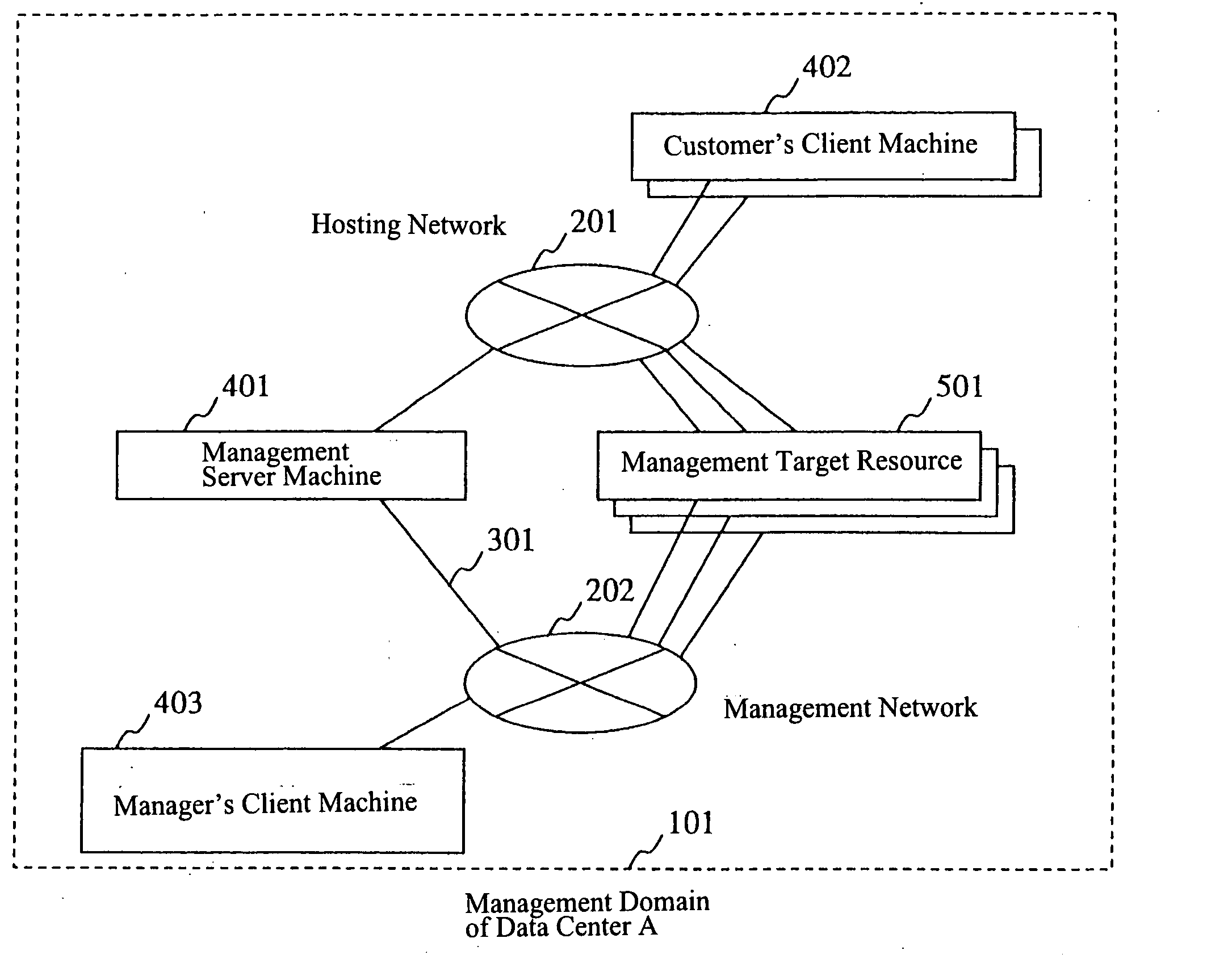
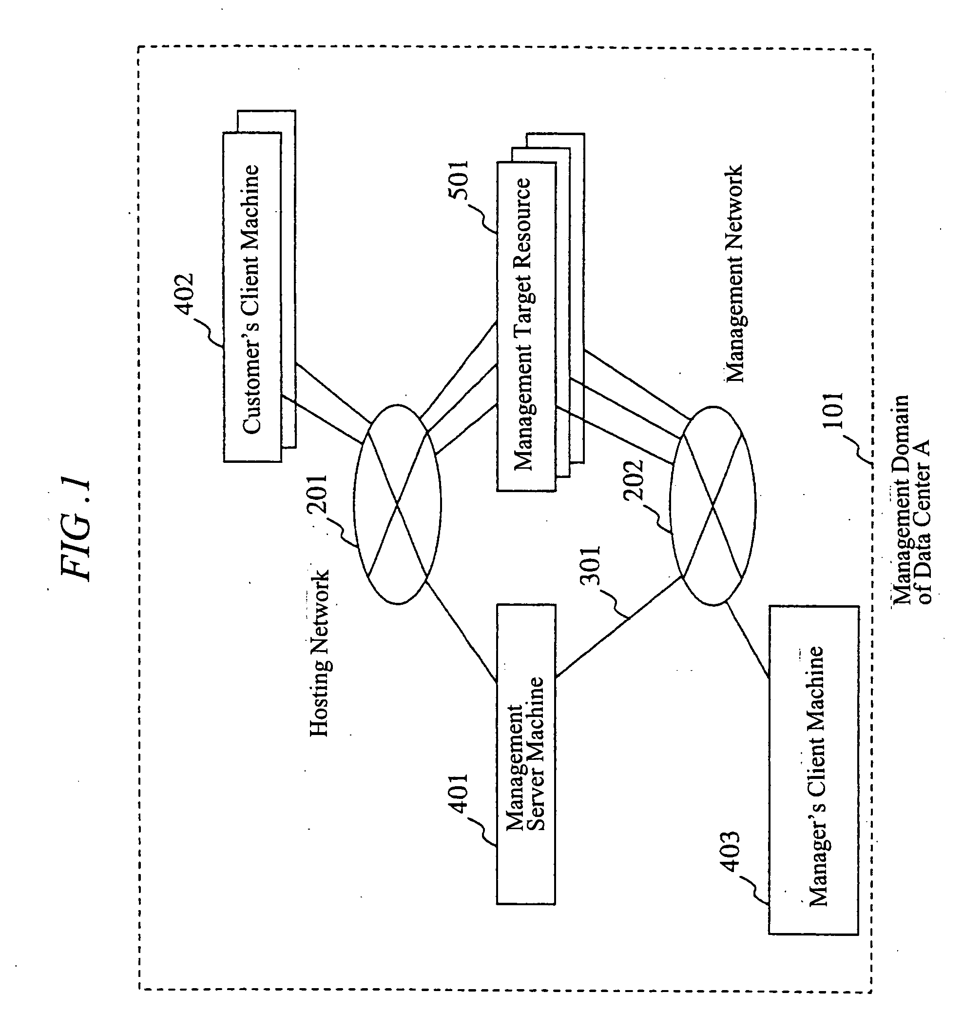
[0131] The configuration of a network, a server computer, and the like to be premised in the present embodiment is same as the system configuration in the first embodiment (FIG. 1).
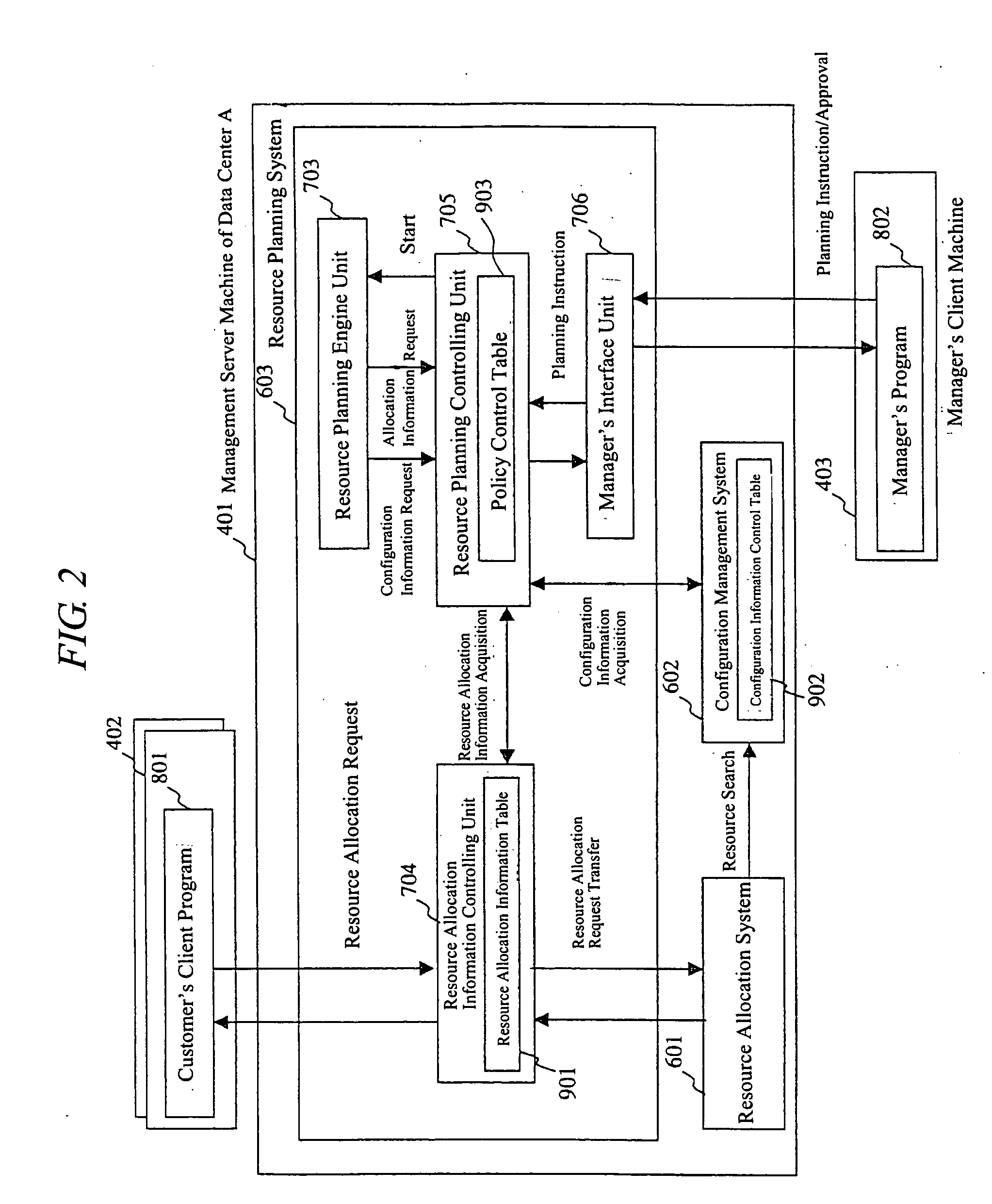
[0132] Next, a program configuration of the entire system will be explained below. FIG. 18 shows a program configuration in the present embodiment, wherein a planning history accumulating unit 708 is added in the resource planning system 603 in comparison with the program configuration in the first embodiment (FIG. 2), so that the h...
fourth embodiment
[0140]FIG. 24 shows a fourth embodiment, and there will below be described an operation of a resource planning system for planning the resource that the data center A should provide next and for consequently adding / deleting necessary software license, on the basis of the resource allocation request from the client, which provides a plurality of computer resources to the client and is assumed by a certain data center A and is accumulated in advance, and the configuration of provision resources in the data center A.
[0141] First, the configuration of networks, server computers and the likes that are premised will be explained. FIG. 24 shows the entire system including the data center A in the present embodiment. In comparison with the system configuration diagram in the second embodiment (FIG. 11), a license server machine 406 connected to Internet 203 is added thereto and is connected to the data center A via the gateway 405. The license server machine 406 provides a server function ...
PUM
 Abstract
Description
Claims
Application Information
 - R&D
- Intellectual Property
- Life Sciences
- Materials
- Tech Scout
- Unparalleled Data Quality
- Higher Quality Content
- 60% Fewer Hallucinations
Browse by: Latest US Patents, China's latest patents, Technical Efficacy Thesaurus, Application Domain, Technology Topic, Popular Technical Reports.
© 2025 PatSnap. All rights reserved.Legal|Privacy policy|Modern Slavery Act Transparency Statement|Sitemap|About US| Contact US: help@patsnap.com


