
Transducer acceleration compensation with frequency domain amplitude and/or phase compensation

a technology of frequency domain and acceleration compensation, applied in the field of transducers, can solve problems such as errors in measurement and force being considered erroneous

Active Publication Date: 2006-04-06
MTS SYSTEMS CORPORATION
View PDF2 Cites 30 Cited by
  • Summary
  • Abstract
  • Description
  • Claims
  • Application Information

AI Technical Summary

Benefits of technology

[0007] This Summary is provided to introduce some concepts in a simplified form that are further described below in the Detailed Description. This Summary is not intended t

Problems solved by technology

When such transducers are moved or displaced, this motion can cause error (inertial error) in the measurement.
Commonly, this error is attributable to a sensor within the transducer that senses motion of a sensing (often called “active”) member.
However, the force is considered erroneous, because the transducer creates the force itself, i.e. through its motion, and not by some force input.

Method used


Image

  • Transducer acceleration compensation with frequency domain amplitude and/or phase compensation
  • Transducer acceleration compensation with frequency domain amplitude and/or phase compensation
  • Transducer acceleration compensation with frequency domain amplitude and/or phase compensation

Examples


Embodiment Construction

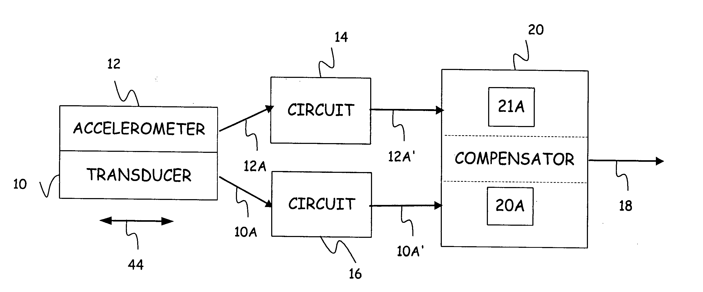
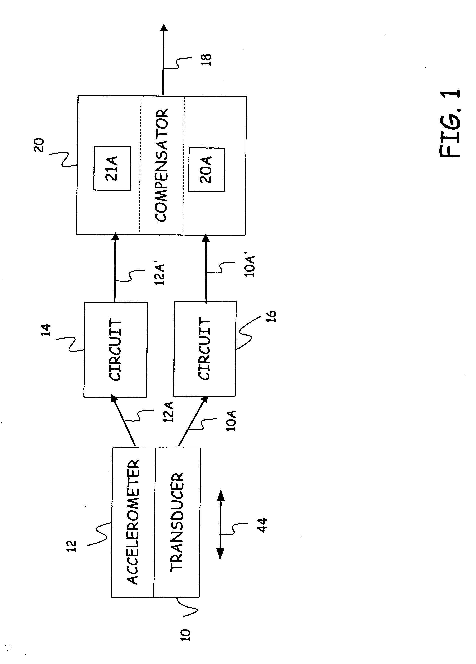
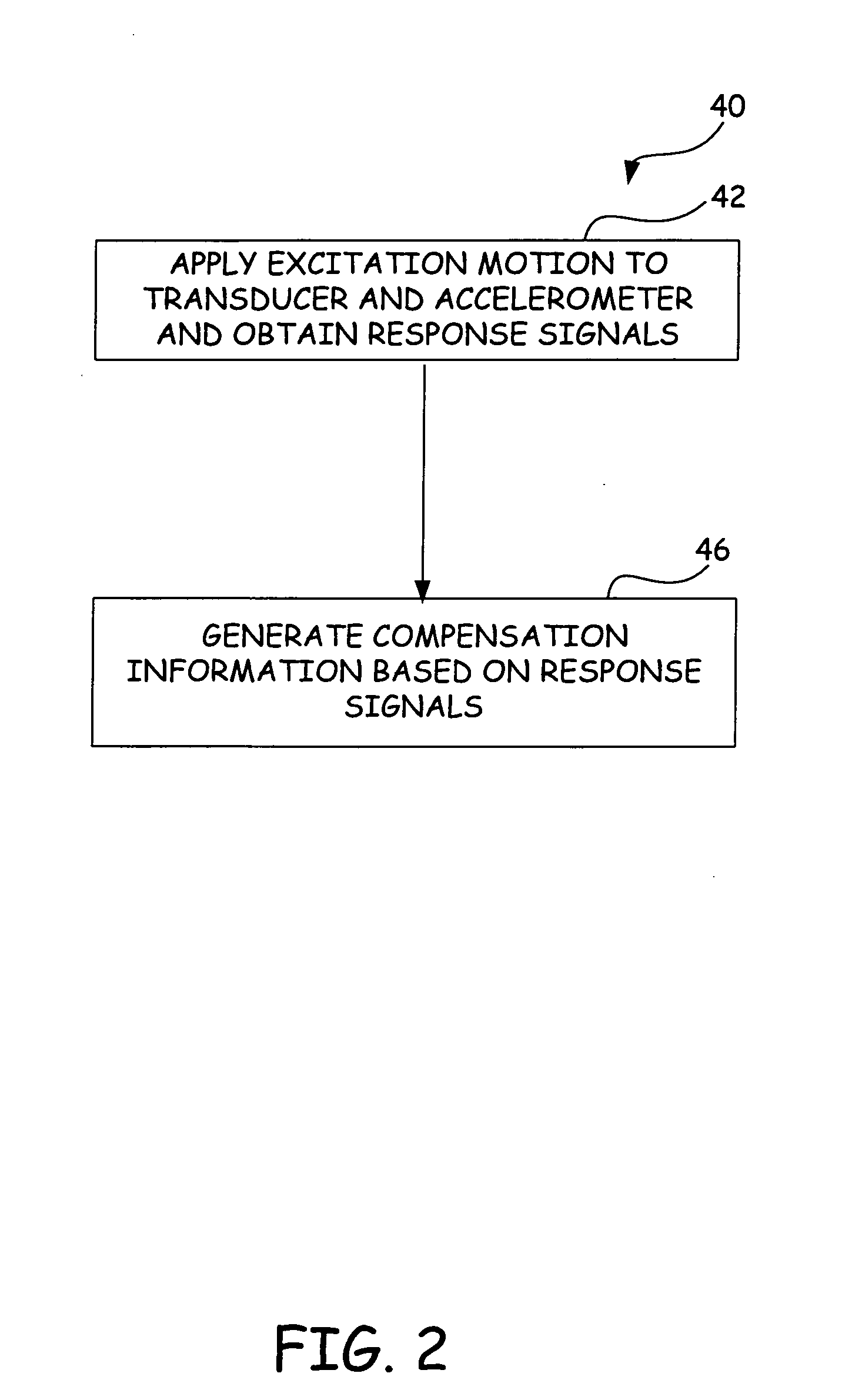
[0012] This description introduces a technique to correct for the inertial error of a transducer as a function of not only a scalar representation for mass (traditional acceleration compensation) but also as a function of frequency (or effective mass coupling). In particular, as one aspect of the present invention, a compensation signal generated from techniques of the present invention provides amplitude and / or phase compensation as a function of frequency.

[0013] As another aspect, this technique also differs from the traditional approach because of this introduction of phase correction. Traditional approaches attempt to match phase as best as possible but do not attempt to apply correction with the knowledge of the phase implemented into the correction scheme. FIG. 1 schematically illustrates a transducer 10 (e.g. force or pressure) and an accelerometer 12, each of which provides an output signal 10A and 12A, respectively. It should be noted in the following description, the term...


PUM


Abstract

A method and system for correcting for the inertial error of a transducer as a function of frequency or effective mass coupling.

Description

CROSS-REFERENCE TO RELATED APPLICATION [0001] The present application is based on and claims the benefit of U.S. provisional patent application Ser. No. 60 / 615,798, filed Oct. 4, 2004, the content of which is hereby incorporated by reference in its entirety.BACKGROUND OF THE INVENTION [0002] The discussion below is merely provided for general background information and is not intended to be used as an aid in determining the scope of the claimed subject matter. [0003] The present invention relates generally to transducers such as force or pressure transducers. More particularly, the present invention relates to improved acceleration compensation for transducers. [0004] Acceleration compensation is a technique that is often used in transducers such as force or pressure transducers. When such transducers are moved or displaced, this motion can cause error (inertial error) in the measurement. Commonly, this error is attributable to a sensor within the transducer that senses motion of a ...

Claims


Application Information

Patent Timeline
IPC IPC(8): G01L25/00
CPCG01L1/26G01L19/02
Inventor SAARI, BYRON J.SODERLING, STEVEN C.
Owner MTS SYSTEMS CORPORATION
Features
  • Generate Ideas
  • Intellectual Property
  • Life Sciences
  • Materials
  • Tech Scout
  • Unparalleled Data Quality
  • Higher Quality Content
  • 60% Fewer Hallucinations
Learn More