Tracheostomy apparatus

a tracheostomy and trachea technology, applied in the field of tracheostomy apparatus, can solve problems such as difficulties in some cases

Inactive Publication Date: 2006-04-06
SMITHS GRP PLC
View PDF27 Cites 28 Cited by
  • Summary
  • Abstract
  • Description
  • Claims
  • Application Information

AI Technical Summary

Problems solved by technology

However, difficulties can arise in some cases.
If there is no way to identify the location of such blood vessels they may inadvertently be cut during the tracheostomy procedure.
This is a particular problem because of the difficulty of stemming blood flow from a cut blood vessel in this region.
The loss of blood

Method used


Image

  • Tracheostomy apparatus
  • Tracheostomy apparatus
  • Tracheostomy apparatus

Examples


Embodiment Construction

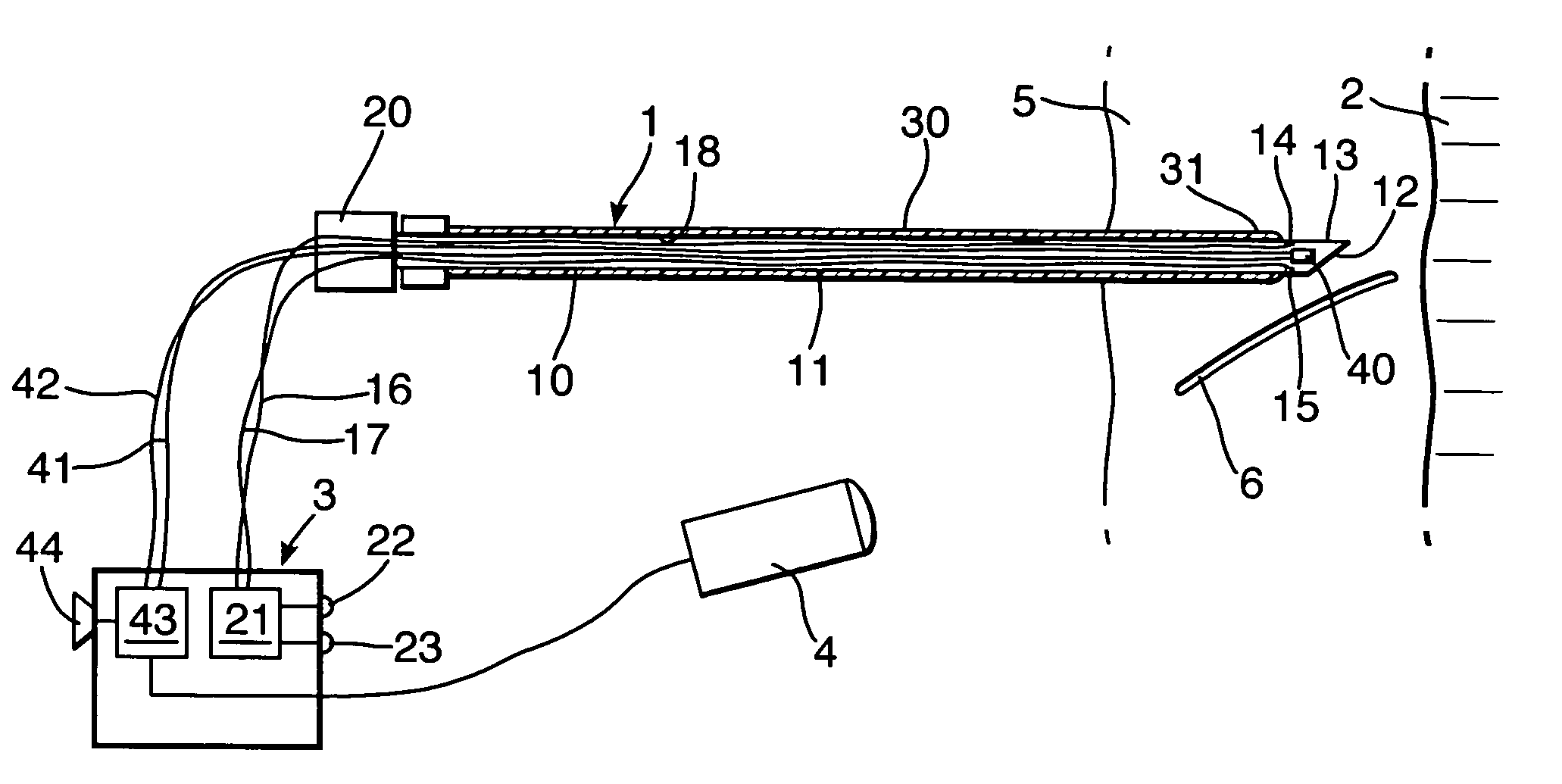
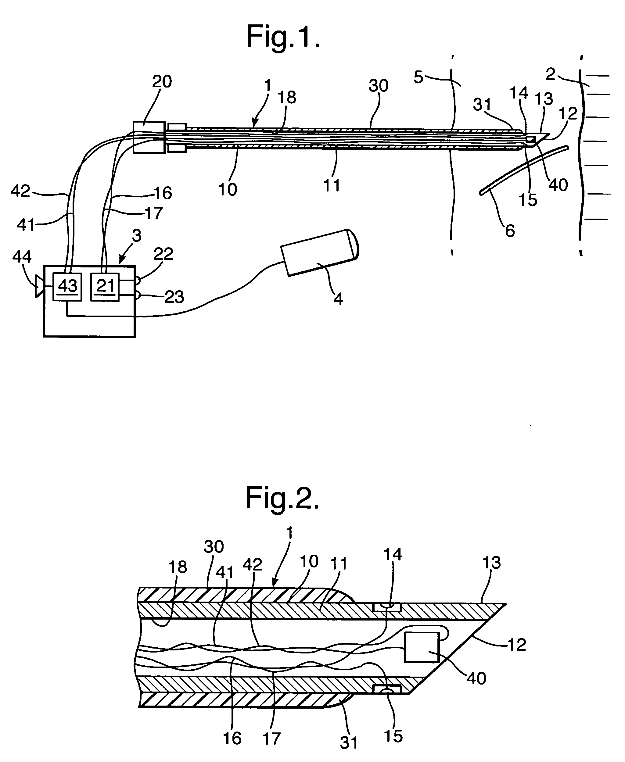
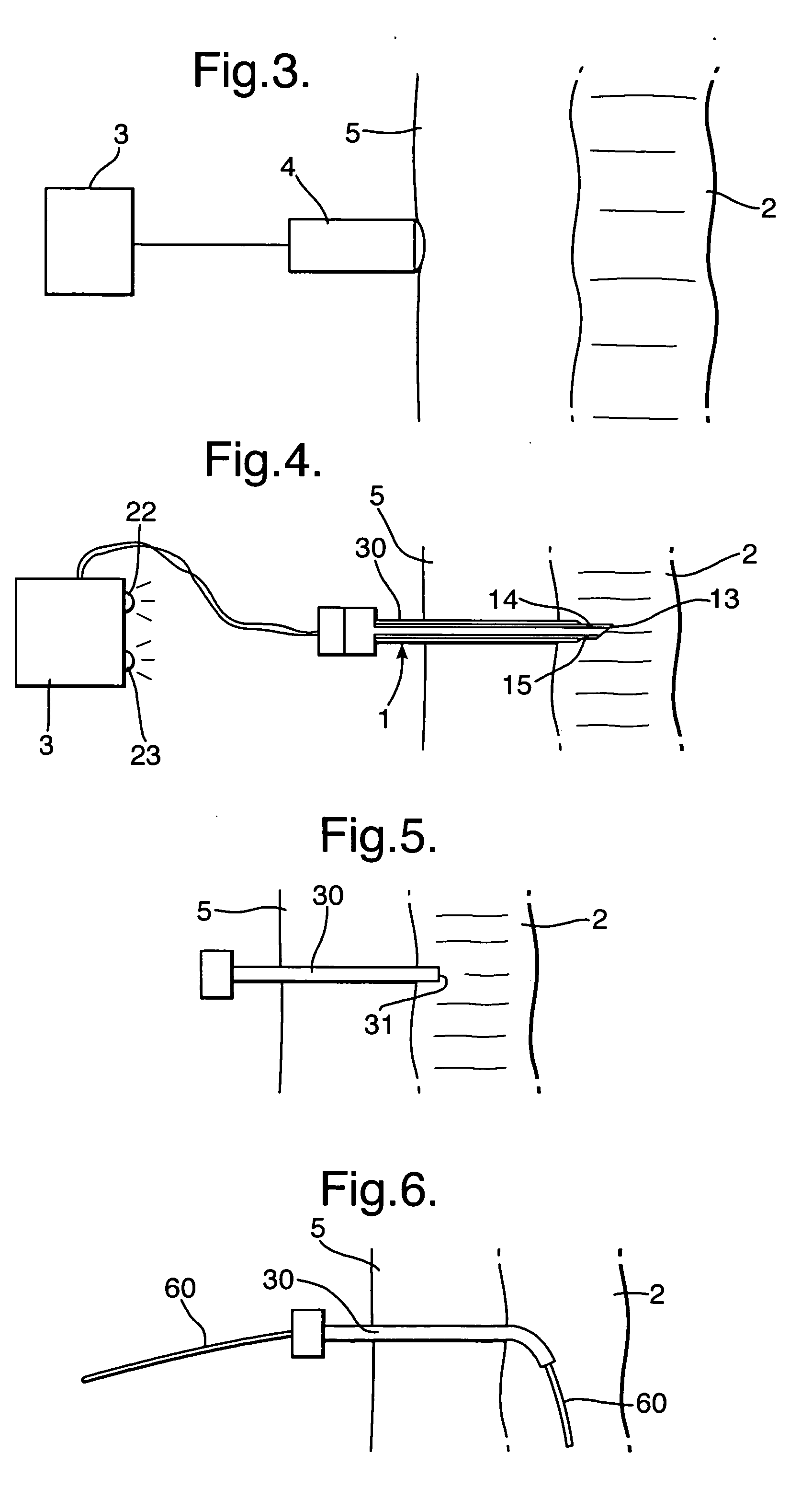
[0016] With reference first to FIGS. 1 and 2, the apparatus includes a probe in the form of a cutting device provided by a needle assembly 1 used to make the initial entry into the trachea 2 and an electrical feedback unit 3 operable to provide feedback to the user of features in the region of the tracheostomy, in particular, of the trachea itself and of large blood vessels. The apparatus also includes an external doppler ultrasound handset 4 connected with the feedback unit 3, which is used for preliminary investigations.

[0017] The probe or needle assembly I includes an inner needle 10 having a rigid, tubular cannula or shaft 11 of a metal and with a bevelled cutting or puncturing tip 12 at its patient end 13. Although the needle is shown as being hollow, it could be solid. On the outer surface of the shaft 11 close to the patient end 13 are two electrodes 14 and 15 spaced from one another around the circumference of the shaft. The electrodes 14 and 15 are exposed on the outside o...


PUM


Abstract

Tracheostomy apparatus includes a needle with a doppler ultrasound transducer mounted within it close to its patient end and connected to a monitor. Two electrodes are insulated from one another on the external surface of the needle close to its patient end. The electrodes are also connected to the monitor. The needle supports a catheter on its outer surface. As the needle is inserted through tissue overlying the trachea, the ultrasound transducer detects the presence of any nearby blood vessels and gives an audible indication on the monitor. The monitor also responds to a rise in impedance between the electrodes indicative of entry of the end of the needle into the trachea so that the needle can be removed to leave the catheter in place. A guide is then inserted through the catheter and the path into the trachea is enlarged with a dilator sufficiently to receive a tracheostomy tube.

Description

BACKGROUND OF THE INVENTION [0001] This invention relates to tracheostomy apparatus. [0002] Many tracheostomies are performed routinely, to aid breathing or ventilation of patients, without problem. However, difficulties can arise in some cases. Whereas in most patients the major blood vessels are located away from the region where the tracheostomy is performed, some patients do have major blood vessels in this region. If there is no way to identify the location of such blood vessels they may inadvertently be cut during the tracheostomy procedure. This is a particular problem because of the difficulty of stemming blood flow from a cut blood vessel in this region. The loss of blood can result in death. Another problem arises, particularly in the percutaneous tracheostomy procedure, of ensuring that the trachea is correctly located by the introducing instruments so that the patient end of the tracheal tube locates within the trachea and not between layers of tissue overlying the trach...

Claims


Application Information

Patent Timeline
IPC IPC(8): A62B9/06A61M16/00A61B17/00A61M16/04A61N1/08
CPCA61B2017/00026A61M16/0472A61N1/08A61M5/427A61M5/46
Inventor BYATT, JOANNATEBBUTT, ADAMTOWNSEND, BARNABY
Owner SMITHS GRP PLC
Why Eureka
Try Eureka