Al technical title is built by PatSnap Al team. It summarizes the technical point description of the patent document.
a fluid container and venting technology, applied in the direction of closures, liquid handling, closures using stoppers, etc., can solve the problems of not exerting sufficient force, achieve the effect of reducing bubble size and noise, improving venting operation, and orienting the closure for us
Inactive Publication Date: 2006-04-06
YOUNG JOHN L
View PDF28 Cites 21 Cited by
Summary
Abstract
Description
Claims
Application Information
AI Technical Summary
This helps you quickly interpret patents by identifying the three key elements:
Problems solved by technology
Method used
Benefits of technology
[0012] When the container is squeezed or the user draws liquid through the mouthpiece, air bubbles enter a vent passageway separated from the flow of exiting liquid by a divider which prevents the air bubbles from becoming entrained. Structure is included to reduce bubble size and noise and improve the venting operation.
[0013] An improved hinged type closure includes a flip cap having an orientation relative to an elongated mouthpiece and a structure so as to better orient the closure for use. The cap will open to a side and away from possible interfering positions with the user's face. The mouthpiece has a shape and structure to improve drinking from the closure and reduce spills or leakage. Supplemental stoppers and plugs also prevent leakage due to sudden forces such as can occur, for example, during transport of a pre-filled liquid container.
Problems solved by technology
The vent openings are sufficiently small in size and placed relative to the main fluid exit so that the weight of the liquid which is in direct contact with the vent openings does not exert sufficient force to overcome surface tension and substantially prevents equalizing air from entering the vent passageways.
Method used
Image
Click on the blue label to locate the original text in one second.
Reading with bidirectional positioning of images and text.
Examples
Embodiment Construction
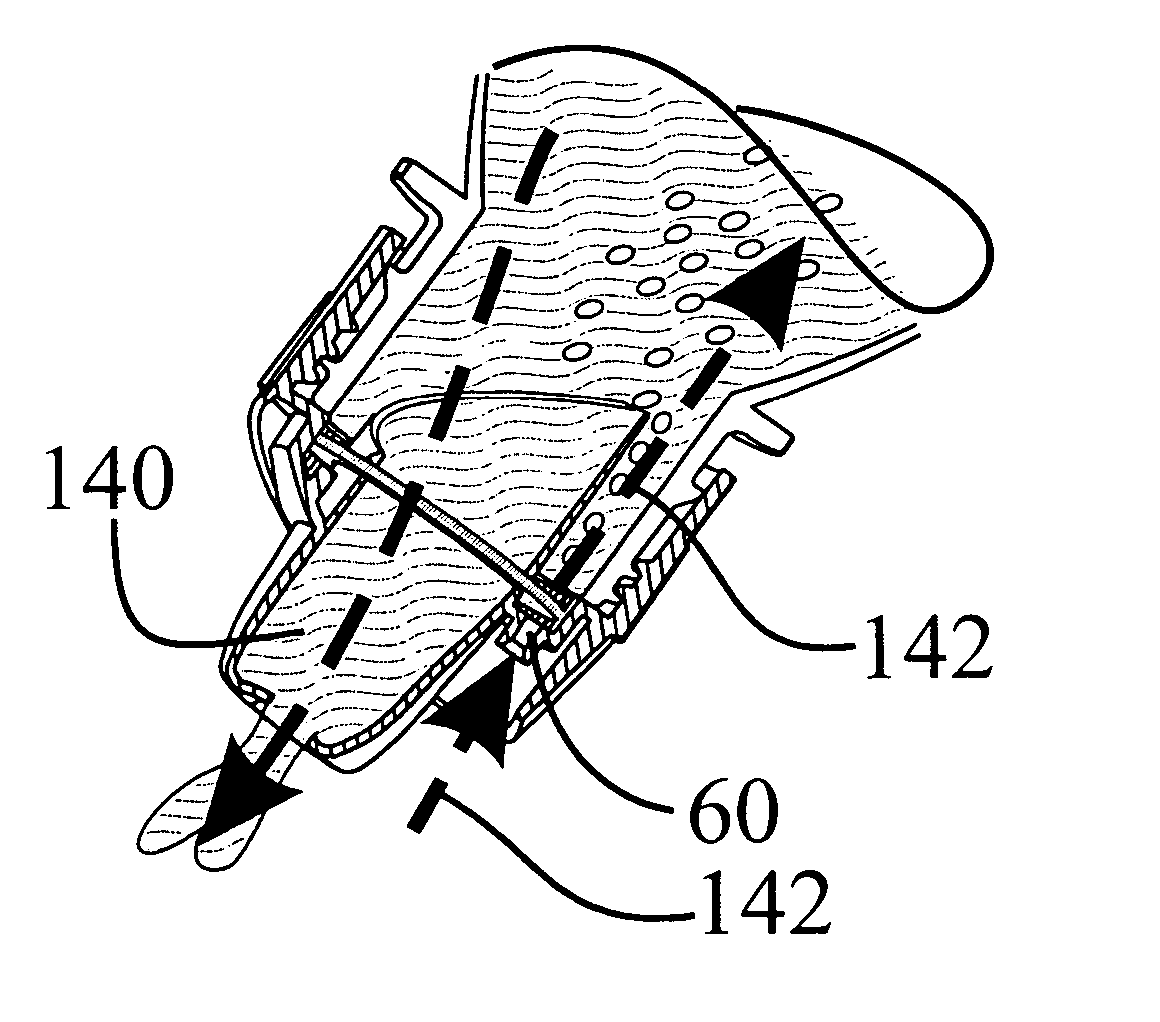
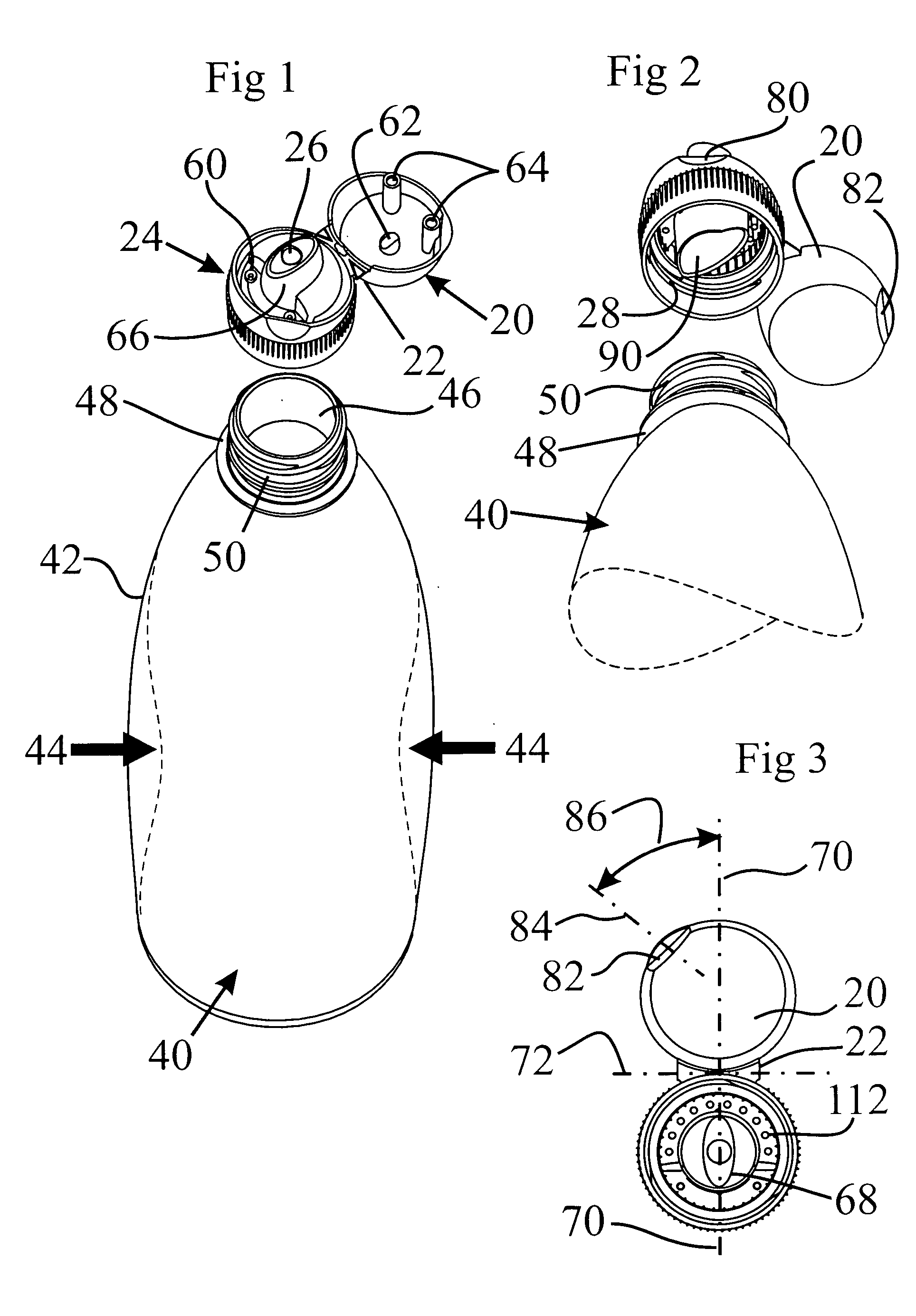
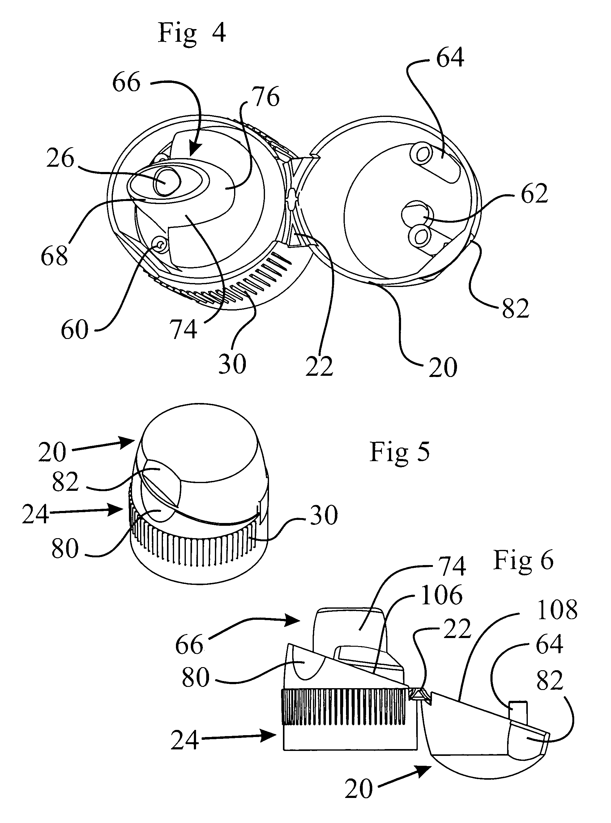
[0025] As seen in FIGS. 1 to 8, a novel vented fluid closure is molded as one piece and includes a top cover or cap 20 which is movably connected by a hinge 22 to a base collar 24 having a central liquid dispensing bore or outlet opening 26. The cap 20 is movable between open positions for dispensing liquid and a closed position as seen in FIG. 5. The collar includes interior threads 28 for mating engagement with a beverage container. An exterior annual wall of the collar 24 includes a large plurality of vertical ribs or splines 30 which are engagable by standard packaging machinery to provide gripping surfaces to assist in threading the interior threads 28 onto the beverage container after the container has been filled during the manufacturing process. These external ribs 30 also assist the user in attaching or detaching the closure from the container.
[0026] The base collar 24 and the cap 20 are adapted to mate with a standard fluid container 40 which may be any container for cont...
PUM
Abstract
A vented closure for a liquid container which will not freely pour includes a cap hinged at one side and movable between open and closed positions relative to a base collar. In an open position, a primary fluid passageway extends through a shaped mouthpiece which is elongated and tapered to conform to a user's mouth. One or more air vents of small size are located in a protected floor of the base collar at positions spaced within predetermined ranges of offsets from the dispensing opening so as to convey liquid into contact with the air vents in a manner to self-seal the air vents by surface tension of the liquid until an unbalance force is present. The cap and collar mate along an offset diagonal edge, and a grip area for the user's thumb or finger is offset from a center line. The offsets cause the cap to flip open with additional clearance and without obstructing a user's nose.
Description
CROSS-REFERENCE TO RELATED APPLICATIONS [0001] This application is a continuation-in-part of my application Ser. No. 10 / 869,603, filed Jun. 16, 2004 entitled “Vented Fluid Closure and Container”, which is a continuation-in-part of my application Ser. No. 10 / 267,306, filed Oct. 9, 2002, entitled “Vented Fluid Closure and Container”, now U.S. Pat. No. 6,779,694, which is a continuation-in-part of my application Ser. No. 09 / 994,303, filed Nov. 26, 2001, entitled “Vented Fluid Container Closure”, now abandoned, which is a continuation-in-part of my application Ser. No. 09 / 736,350, filed Dec. 13, 2000, entitled “Vented Fluid Container Closure”, now abandoned.FIELD OF THE INVENTION [0002] The present invention relates generally to vented fluid closures and containers and, more particularly, to a vented closure for a fluid container with a non-pouring type fluid passage when the closure is open. BACKGROUND OF THE INVENTION [0003] Water and other non-carbonated beverages, and particularly s...
Claims
Application Information
Patent Timeline
Application Date:The date an application was filed.
Publication Date:The date a patent or application was officially published.
First Publication Date:The earliest publication date of a patent with the same application number.
Issue Date:Publication date of the patent grant document.
PCT Entry Date:The Entry date of PCT National Phase.
Estimated Expiry Date:The statutory expiry date of a patent right according to the Patent Law, and it is the longest term of protection that the patent right can achieve without the termination of the patent right due to other reasons(Term extension factor has been taken into account ).
Invalid Date:Actual expiry date is based on effective date or publication date of legal transaction data of invalid patent.
Patent Type & Authority Applications(United States)