Optical reader for diffraction grating-based encoded optical identification elements

an optical identification element and optical reader technology, applied in the field of optical readers for diffraction grating-based encoded optical identification elements, can solve the problems of large size of beads/substrates used for uniquely identifying the probes, insufficient existing technologies, and insufficient radio-frequency identification (rfid), etc., and achieve the effect of reducing the size of existing technologies

Active Publication Date: 2006-04-06
ILLUMINA INC
View PDF98 Cites 68 Cited by
  • Summary
  • Abstract
  • Description
  • Claims
  • Application Information

AI Technical Summary

Benefits of technology

[0011] Objects of the present invention include provision of a reader for an optical identification elements where the elements may have a large number of distinct codes, may be made very small (depending on the application) and / or can withstand harsh environments.
[0014] The reader of the present invention optimizes fluorescent measurements when microbeads having a cylindrical shape are used, while minimizing sensitivity to beam positioning and / or bead misalignment.
[0015] In addition, the invention can easily identify a bead and the code therein along a scan having many beads along a row and compensates for uneven, jagged, and / or inconsistent surface geometries for the end effects of the beads, as well as when beads densely packed end-to-end.
[0016] Further, because the code is projected and read in the “far field” or Fourier plane, the reader of the present invention does not require expensive imaging and magnifying optics to create a high resolution magnified image of the bead to read the code. This is different from prior readers which actually image the bead itself to determine the code, e.g., for small particles that have bar codes printed on them.
[0020] The present invention reads the code in the element as well as any fluorescence that may exist on the microbeads. In addition, the invention may use the same laser to both interrogate the code and read a fluorescent signal from the bead, without interference between the two, thereby saving cost and time.
[0022] In addition to reading the bead code and / or fluorescence, the reader can determine the precise location of each bead read in the bead cell, and can then return to any given bead for further review and / or analysis if desired. This feature also allows the reader to be used as a bead “mapper”, i.e., to identify or map the exact location of each bead on a planar surface. Also, the reader could use fluorescent “tracer” beads having a predetermined fluorescent signal, different from the other beads, which would allow the reader to map the locations of all the beads based on the location of the tracer beads. Further, once the location of the beads in a cell are mapped, the bead cell can be used in another reader or scanner for review and / or analysis. Other techniques may also be used to orient the reader to a predetermined calibration or standard cell location from which all the beads may be mapped if desired.

Problems solved by technology

Such existing beads / substrates used for uniquely identifying the probes, however, may be large in size, have a limited number of identifiable codes, and / or made of a material not suitable to harsh environmental conditions, such as, harsh temperature, pressure, chemical, nuclear and / or electromagnetic environments.
Existing technologies, such as bar codes, electronic microchips / transponders, radio-frequency identification (RFID), and fluorescence (or other optical techniques), are often inadequate.
For example, existing technologies may be too large for certain applications, may not provide enough different codes, cannot be made flexible or bendable, or cannot withstand harsh environments, such as, harsh temperature, pressure, chemical, nuclear and / or electromagnetic environments.

Method used


Image

  • Optical reader for diffraction grating-based encoded optical identification elements
  • Optical reader for diffraction grating-based encoded optical identification elements
  • Optical reader for diffraction grating-based encoded optical identification elements

Examples


Embodiment Construction

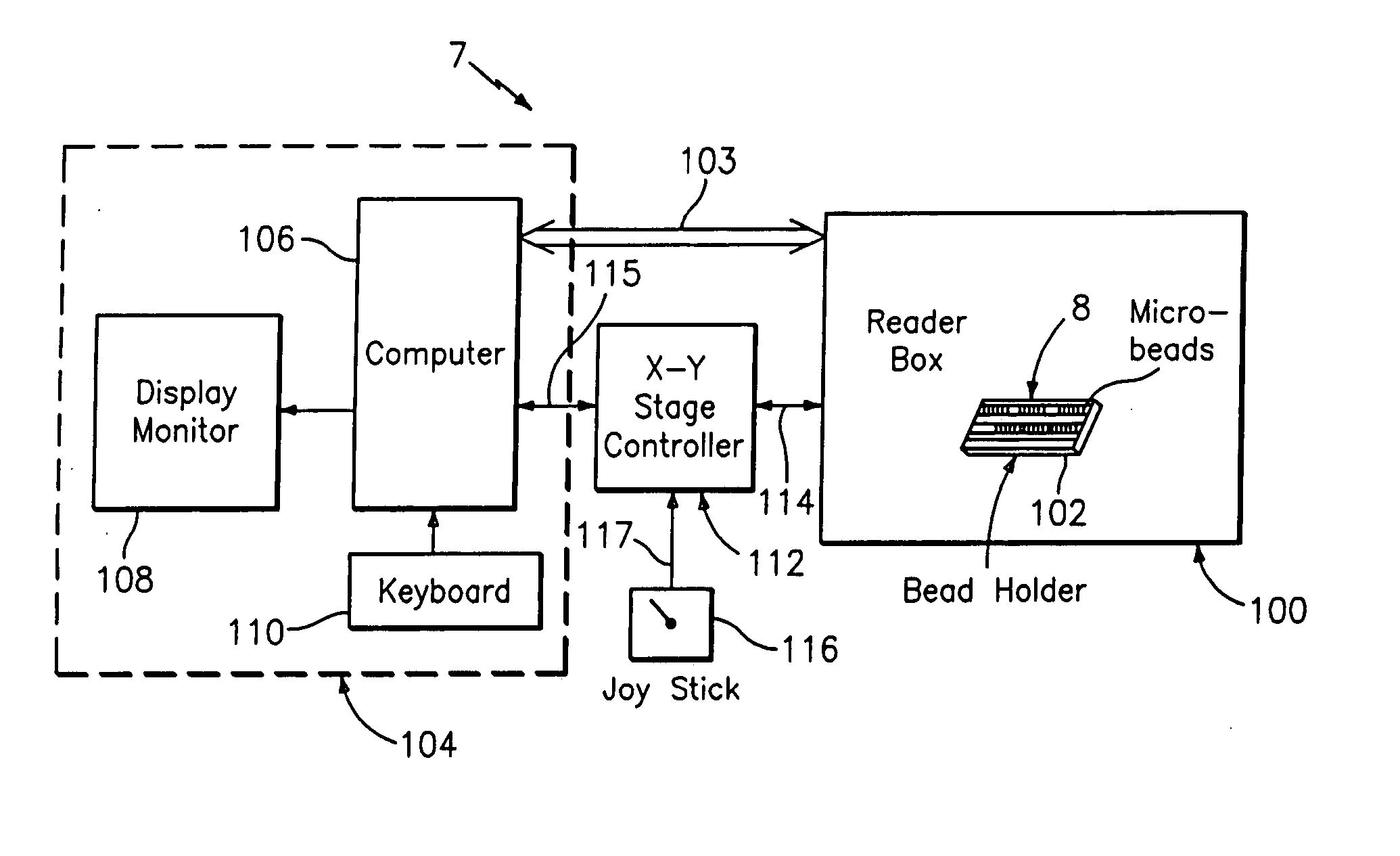
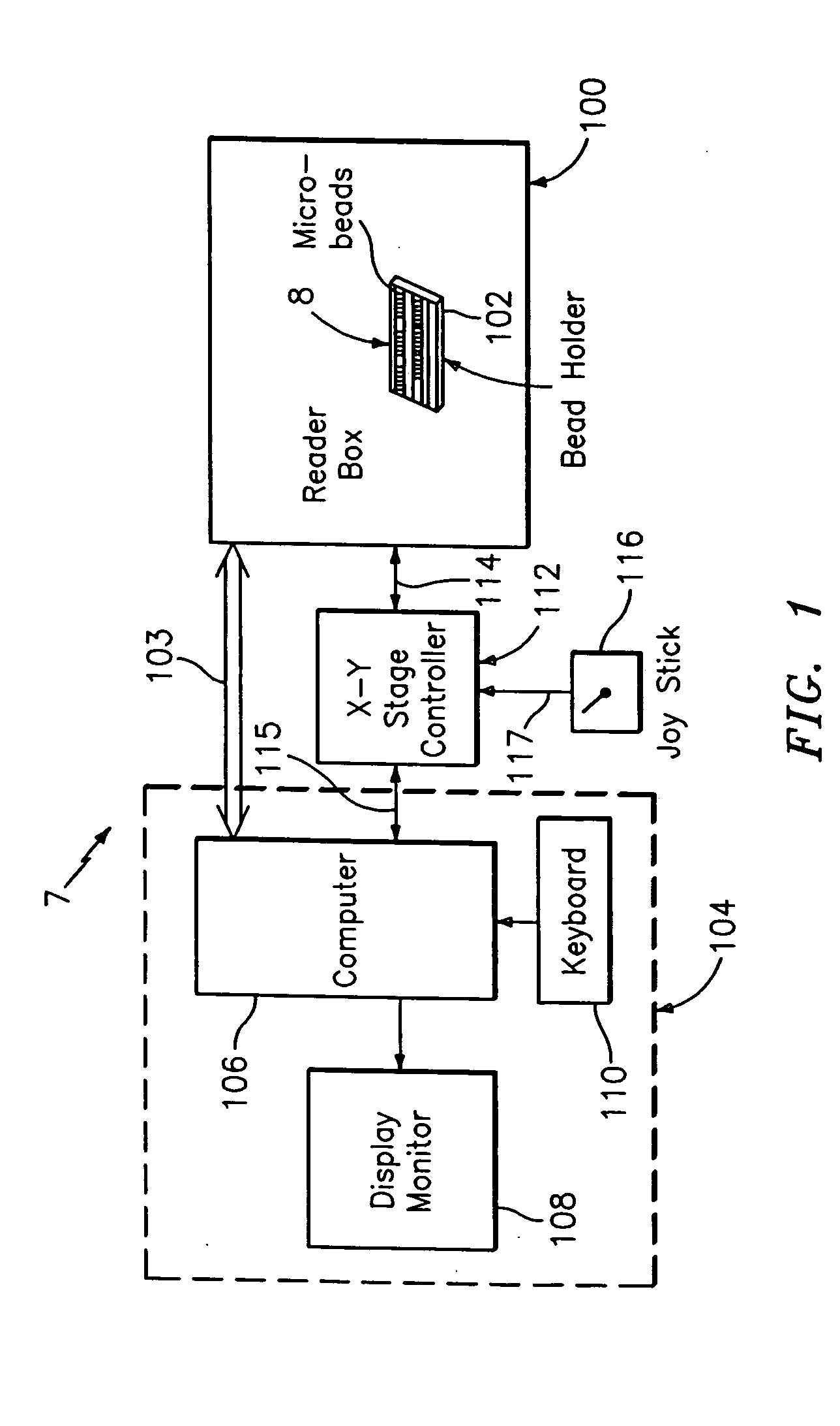
[0081] Referring to FIG. 1, an optical reader system 7 for diffraction grating based encoded optical identification elements (such as microbeads), comprises a reader box 100, which accepts a bead cell (or holder or cuvette or chamber) 102 that holds and aligns the microbeads 8 which have embedded codes therein. The reader box 100 interfaces along lines 103 with a known computer system 104 having a computer 106, a display monitor 108, and a keyboard. In addition, the reader box 100 interfaces along lines 114 with an stage position controller 112 and the controller 112 interfaces along a line 115 with the computer system 104 and a manual control device (or joy stick) 116 along a line 117.

[0082] The microbeads 8 are similar to or the same as those described in pending US patent application Ser. No. 10 / 661,234 (CyVera Docket No. CV-0038A), entitled Diffraction Grating Based Optical Identification Element, filed Sep. 12, 2003, which is incorporated herein by reference in its entirety, d...


PUM


Abstract

An optical reader system 7 for diffraction grating-based encoded microbeads (or bead reader system), comprises a reader box 100, which accepts a bead cell (or cuvette) 102 that holds the microbeads 8, having an embedded code therein. The reader box 100 interfaces along lines 103 with a known computer system 104. The reader box 100 interfaces with a stage position controller 112 and the controller 112 interfaces along a line 115 with the computer system 104 and a manual control device (or joy stick) 116 along a line 117. The reader interrogates the microbeads to determine the embedded code and / or the fluorescence level on the beads. The reader provides information similar to a bead flow cytometer but in a planar format, i.e., a virtual cytometer.

Description

CROSS REFERENCES TO RELATED APPLICATIONS [0001] This application claims the benefit of U.S. Provisional Patent Applications, Ser. No. 60 / 410,541 (CyVera Docket No. CV-0026PR), filed Oct. 1, 2003, Ser. No. 60 / 512,302 (CyVera Docket No. CV-0046PR), filed Oct. 17, 2003; Ser. No. 60 / 513,053 (CyVera Docket No. CV-0047PR), filed Oct. 19, 2003; Ser. No. 60 / 546,435 (CyVera Docket No. CV-0053PR), filed Feb. 19, 2004; Ser. No. 60 / 610,829 (CyVera Docket No. CV-0088PR), filed Sep. 17, 2004 ; and is a continuation-in-part of U.S. patent application, Ser. No. 10 / 661,234 (CiDRA Docket No. CV-0038A), which is a continuation-in-part of U.S. patent application, Ser. No. 10 / 645,689 (CyVera Docket No. CC-0638), which claimed the benefit of U.S. provisional applications, Ser. No. 60 / 405,087 (CyVera Docket No. CV-0005PR / Prior CC-0429PR) filed Aug. 20, 2002 and Ser. No. 60 / 410,541 (CyVera Docket No. CV-0012PR / Prior CC-0543 PR), filed Sep. 12, 2002; and is a continuation-in-part of U.S. patent application,...

Claims


Application Information

Patent Timeline
Patent Type & Authority Applications(United States)
IPC IPC(8): G06K7/10
CPCB01J2219/005B01J2219/0056G06K7/1094G06K7/12G06K19/06009G06K2019/06225G06K2019/06234G06K2019/0629G07D7/0013G07D7/004G07D7/0032
Inventor MOON, JOHN A.FOURNIER, DAVID R.PUTNAM, MARTIN A.KERSEY, ALAN D.LI, TUO
Owner ILLUMINA INC
Why Eureka
Try Eureka