Brushless motor

a brushless motor and inner rotor technology, applied in the direction of mechanical energy handling, dynamo-electric components, control/drive circuits, etc., can solve the problems of unsatisfactory engagement with the mating gear, difficult to reduce the size of the motor, adverse effect on the mating part, etc., to improve the coaxiality of the bearings, reduce the height of the motor in axial direction, and eliminate the effect of assembly errors

Active Publication Date: 2006-04-06
NIDEC CORP
View PDF6 Cites 34 Cited by
  • Summary
  • Abstract
  • Description
  • Claims
  • Application Information

AI Technical Summary

Benefits of technology

[0015] Accordingly, it is an object of this invention to provide a compact brushless motor in which the bearing is fitted on the housing to improve the accuracy of the rotary shaft on the one hand and the internal heat of the motor is discharged on the other hand.
[0017] In this brushless motor described above, the housing is erected on the inside of the rotor yoke, and the bearings are arranged along the height in axial direction in the rotor yoke. Therefore, the height of the motor in axial direction can be reduced. Also, the bearings are arranged on a single housing. As compared with a case in which the bearings are arranged on different parts, therefore, the error due to the assembly of different parts is eliminated and the coaxiality of the bearings improved. As a result, the accuracy of the rotary shaft inserted in the bearings is improved.

Problems solved by technology

This also makes it difficult to reduce the size of the motor.
As a result, the rotary shaft member A1 deviates from the rotational center axis and wobbles, thereby often having an adverse effect on a mating part to which the force is transmitted from the rotary shaft member A1.
In the case where a gear is fitted on the forward end of the rotary shaft member A1 to transmit the force through a mating gear in mesh, for example, a low coaxiality of the rotary shaft member A1 would lead to an unsatisfactory engagement with the mating gear, and imposes an offset load on the gears of both the motor and the mating part.
Once at least one of the gears of the motor and the mating part is damaged, the gear may be cut or dented.
Further, the cut or the dent may cause a bite failure, generating vibrations and noises.
In the worst case, the gear may be broken, thereby causing a fatal malfunction of the electronic device carrying the motor.

Method used


Image

  • Brushless motor
  • Brushless motor
  • Brushless motor

Examples


Embodiment Construction

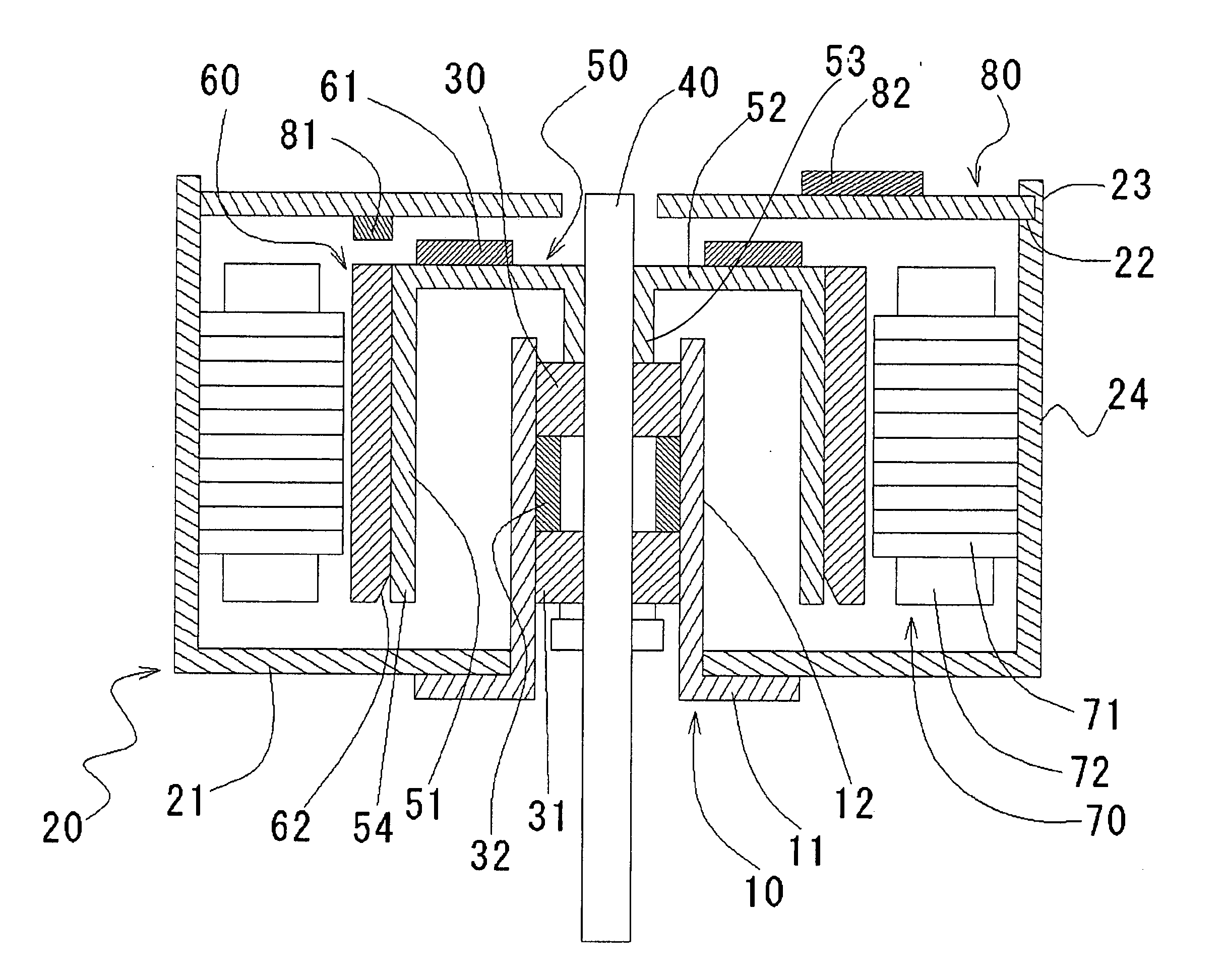
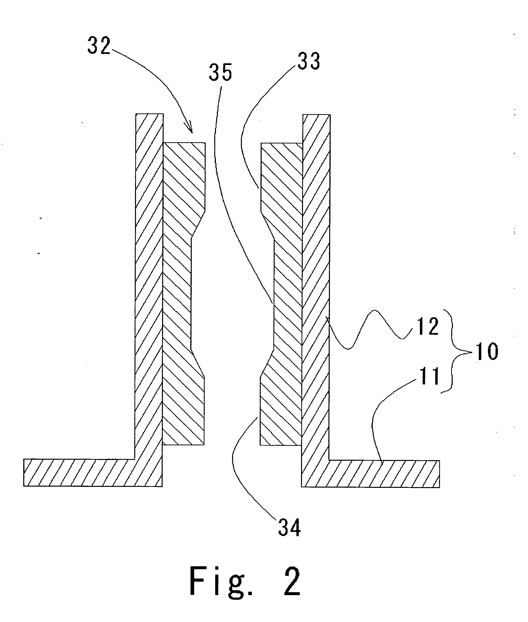
[0025] An embodiment of the invention is explained below with reference to the drawings. For facilitating the understanding, the vertical direction in FIG. 1 is described as “axially vertical direction”, to which the actual mounting position of a motor is not limited.

[0026] First, the whole motor structure is explained with reference to FIG. 1.

[0027] A cover 20 for covering an outer part of the motor having the shape of a bottomed cylinder includes a bottom surface portion 21 downward and with a open end upward and a cover cylindrical portion 24. A through hole is formed in the central part of the bottom surface portion 21 of the cover 20.

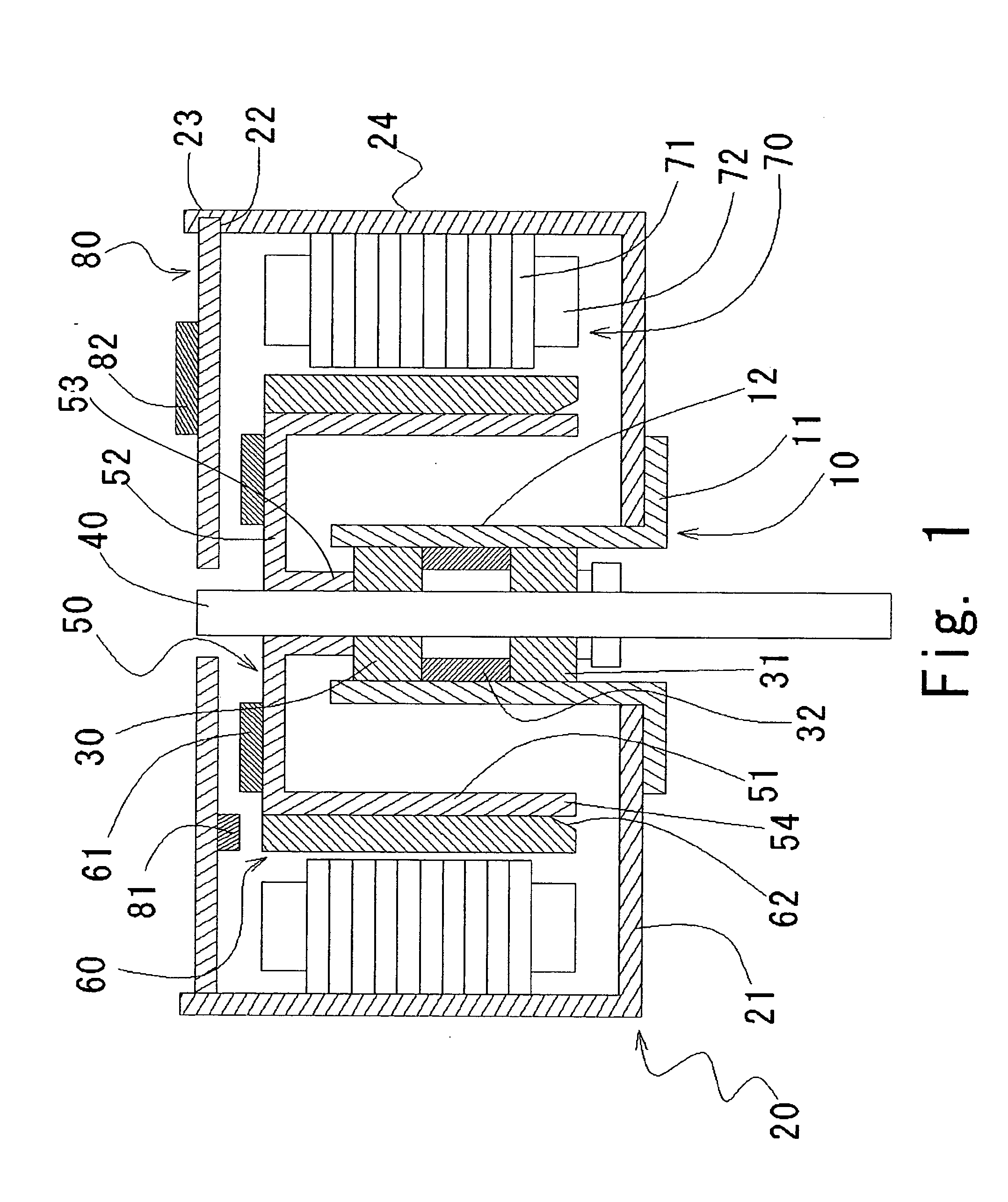
[0028] A housing 10 has the shape of a hollow cylinder. The housing 10 has, in the lower part thereof as viewed in axial direction, a hook 11 connected fixedly with a central portion of the bottom surface of the cover and a housing cylindrical portion 12 located at a rotationally symmetric location around the rotary shaft. Two bearings 30, 31 ar...


PUM


Abstract

A compact, highly accurate and inexpensive brushless motor is disclosed. A bearing is fixed to the inner periphery of a cylindrical portion of a housing, and a shaft is rotatably inserted through the bearing to cover the housing. A yoke arranged at the forward end of the cylindrical portion of the housing is fixed on the shaft. In this configuration, the bearing is arranged at a position on the inside of the yoke, and therefore the motor can be reduced in size to the extent of superposition between the yoke and the housing. The bearing is fixed to one member of the housing, and therefore a high accuracy is realized.

Description

BACKGROUND OF THE INVENTION [0001] 1. Field of the Invention [0002] This invention relates to an inner rotor-type brushless motor having a slide bearing. [0003] 2. Description of the Related Art [0004] Many electronic devices acquire power from a motor. In recent years, with the reduction in size and price and the increase in accuracy of the electronic devices, demand has increased for smaller, inexpensive and more accurate motors used in the electronic devices. [0005] A sectional view, as taken in axial direction, of the structure of the conventional inner rotor-type brushless motor is shown in FIG. 7. [0006] The brushless motor shown in FIG. 7 includes a rotor A with a rotary shaft member A1 inserted thereon, bearings B1, B2 for rotatably supporting the rotor A, a stator C, a circuit board D and covers E1, E2 for accommodating these component parts. [0007] The rotor A has a structure in which the rotary shaft member A1 fitted in an inner through hole of a cylindrical rotor core A2...

Claims


Application Information

Patent Timeline
Patent Type & Authority Applications(United States)
IPC IPC(8): H02K11/00
CPCH02K1/2733H02K5/1675H02K11/0073H02K29/08H02K29/14H02K11/33
Inventor FUJII, YOSHIO
Owner NIDEC CORP
Why Eureka
Try Eureka