Detection of pump cavitation/blockage and seal failure via current signature analysis

a technology of current signature analysis and pump cavitation, which is applied in the direction of emergency protective arrangements for limiting excess voltage/current, mechanical power/torque control, emergency protective arrangements for automatic disconnection, etc., can solve the problem of not being able to provide particular fault information, and achieve the effect of reducing cost curren

Inactive Publication Date: 2006-04-06
ROCKWELL AUTOMATION TECH
View PDF17 Cites 103 Cited by
  • Summary
  • Abstract
  • Description
  • Claims
  • Application Information

AI Technical Summary

Benefits of technology

[0008] The present invention provides for a system and method for condition monitoring of synthesized fault data and determining an operating condition of a pump. It has been found that fault data relating to the operating condition of a pump is encoded in variations in current of a motor driving the pump. These features present in the stator frequency spectrum of the motor stator current are caused by load effects of the pump on the motor rather than changes in the motor itself. The present invention provides a system and method for extracting (e.g., synthesizing) the fault data directly from the instantaneous motor current data. This data relates not only to pump machinery conditions, but also pump process conditions. Thus, by employing current signature analysis of the instantaneous current of the motor driving the pump, problems with the pump and / or process line can be detected without using invasive and expensive pressure and flow meters. Instead, a lower cost current sensor may be used and this sensor may be located in a motor control center or other suitable location remote from the motor and pump.

Problems solved by technology

Furthermore, it is desired to further post process the output generated by unsupervised ANN based decision modules for condition monitoring applications.
This is because unsupervised ANN based decision modules when presented with a new operating condition can only signal the formation of a new output entry indicating that a possible new condition has occurred, but is not necessarily able to provide particular fault information.

Method used


Image

  • Detection of pump cavitation/blockage and seal failure via current signature analysis
  • Detection of pump cavitation/blockage and seal failure via current signature analysis
  • Detection of pump cavitation/blockage and seal failure via current signature analysis

Examples


Embodiment Construction

[0047] The present invention will now be described with reference to the drawings, wherein like reference numerals are used to refer to like elements throughout. As is mentioned above, the present invention relates to a system and method for using synthesized fault data encoded in the instantaneous current of a motor driving a pump for pump diagnosis and failure prediction. One particular aspect of the present invention employs a neural network to monitor the synthesized fault data in order to diagnose the operating condition of the pump. As previously mentioned, it is to be appreciated that the present invention can be applied to monitoring both the pump and the motor driving the pump simultaneously.

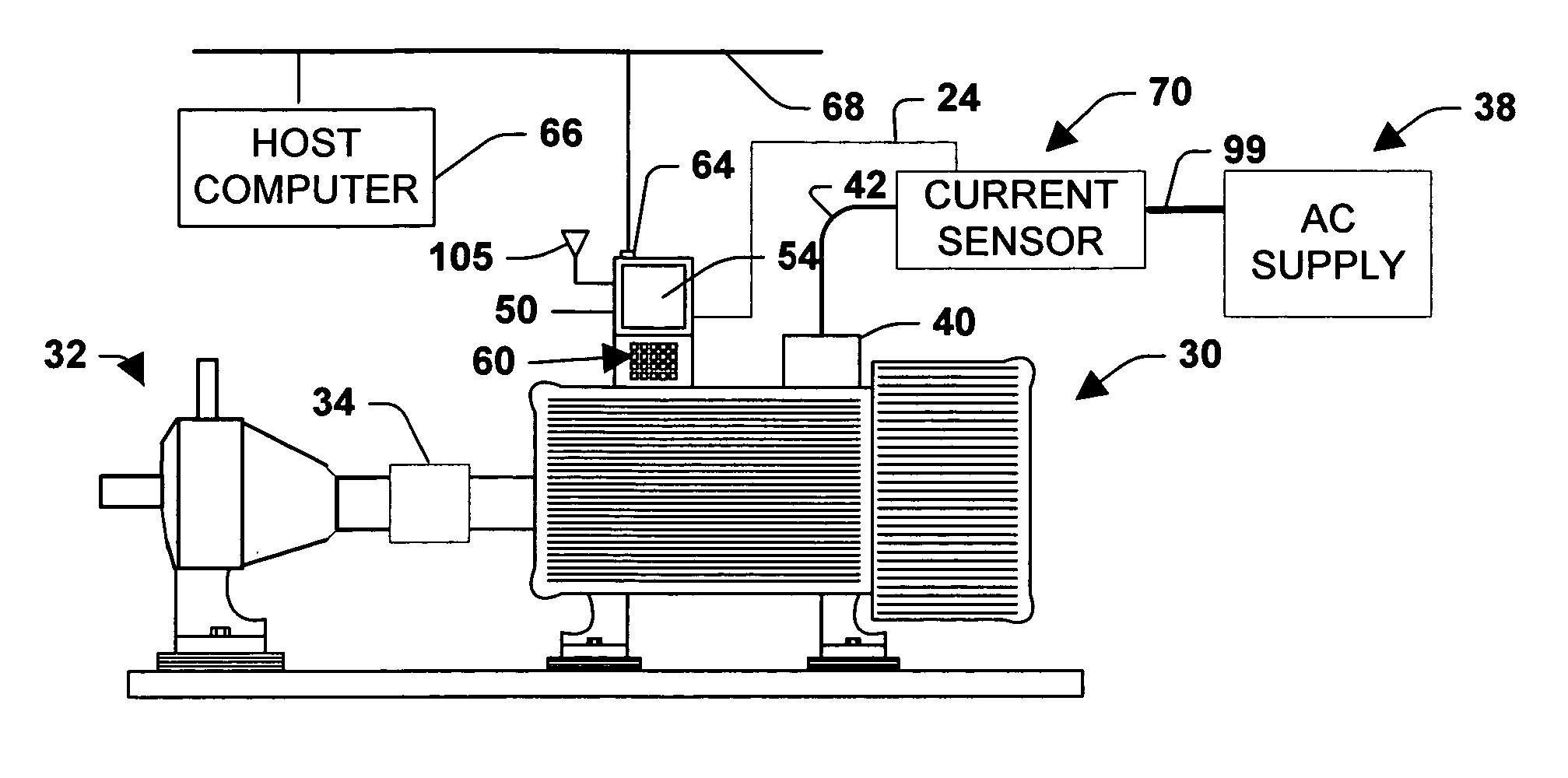
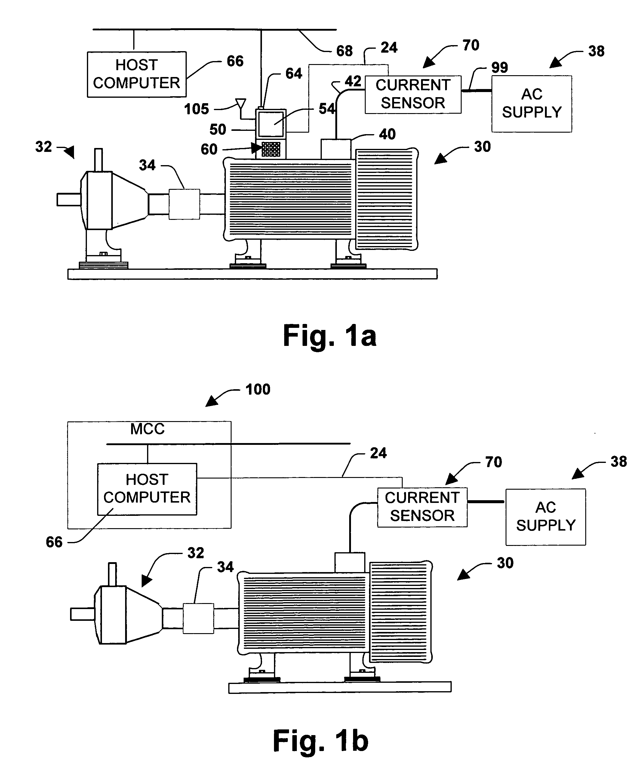
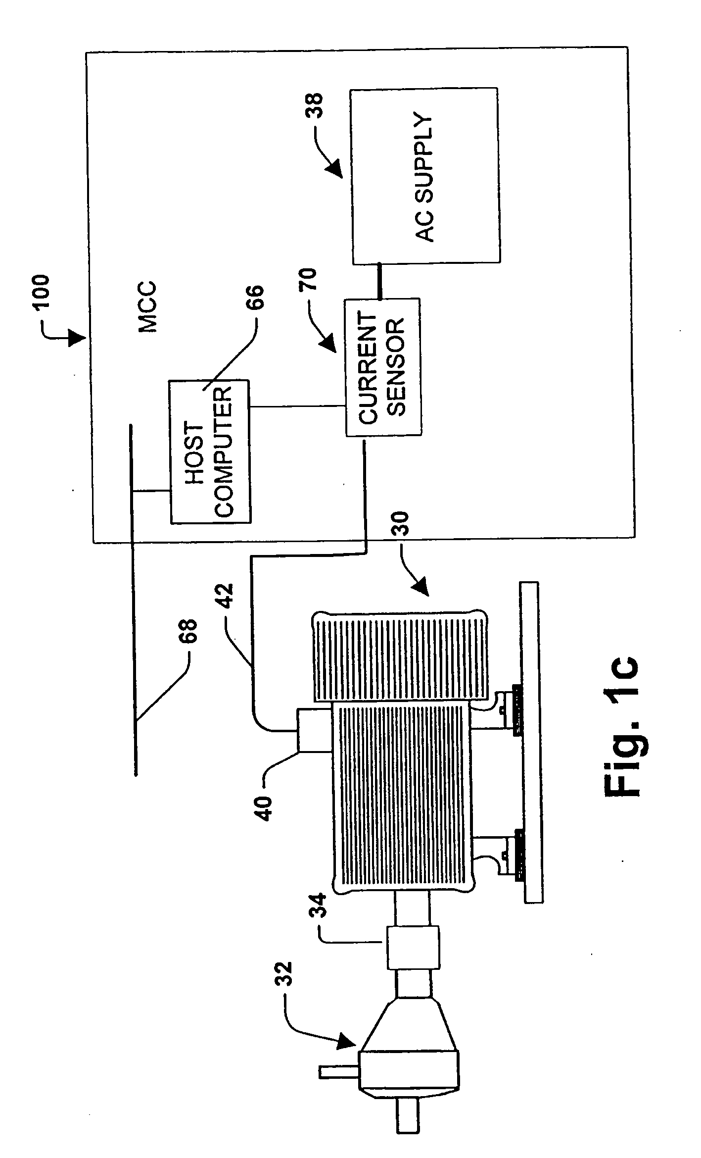
[0048] Referring initially to FIGS. 1a and 2, one specific environment in which the present invention may be employed is shown. A three-phase AC induction motor 30 is depicted driving a pump 32 through a shaft coupling 34. Alternatively, a single shaft without a coupling could be provi...


PUM


Abstract

A system and method is provided for monitoring the operating condition of a pump by evaluating fault data encoded in the instantaneous current of the motor driving the pump. The data is converted to a frequency spectrum which is analyzed to create a fault signature having fault attributes relating to various fault conditions associated with the pump. The fault signature is then input to a neural network that operates in conjunction with a preprocessing and post processing module to perform decisions and output those decisions to a user interface. A stand alone module is also provided that includes an adaptive preprocessing module, a one-shot unsupervised neural network and a fuzzy based expert system to provide a decision making module that operates with limited human supervision.

Description

CROSS-REFERENCE TO RELATED APPLICATIONS [0001] This application is a continuation of U.S. patent application Ser. No. 10 / 824,899, filed on Apr. 15, 2004, and entitled “DETECTION OF PUMP CAVITATION / BLOCKAGE AND SEAL FAILURE VIA CURRENT SIGNATURE ANALYSIS”, which is a continuation of U.S. Ser. No. 09 / 407,617, filed on Sep. 28, 1999, entitled “DETECTION OF PUMP CAVITATION / BLOCKAGE AND SEAL FAILURE VIA CURRENT SIGNATURE ANALYSIS”. The entirety of these applications are incorporated herein by reference.TECHNICAL FIELD [0002] The present invention generally relates to a system and method for obtaining and using synthesized fault data for pump diagnosis and failure prediction. BACKGROUND OF THE INVENTION [0003] Motors, pumps and bearings require frequent maintenance attention in typical commercial systems and industrial plants. With conventional maintenance strategies such as exception-based and periodic-checking, faults developed in critical equipment (e.g. pumps) have to be detected by h...

Claims


Application Information

Patent Timeline
Patent Type & Authority Applications(United States)
IPC IPC(8): G01R31/08F04D15/00F04D29/66G01B5/28G01B5/30G01R31/28G01R31/34G06E1/00G06E3/00G06F15/18G06F19/00G06G7/00H02H3/00H02H9/08
CPCF04D15/0077F04D15/0088F04D29/669G01R31/2846G01R31/343G06N3/088G06N5/048Y10S706/904Y10S706/906Y10S706/907Y10S706/905
Inventor UNSWORTH, PETER J.DISCENZO, FREDERICK M.BABU, VETCHA SARAT
Owner ROCKWELL AUTOMATION TECH
Why Eureka
Try Eureka