Positioning device and lithographic apparatus

a positioning device and positioning device technology, applied in the direction of photomechanical devices, instruments, optics, etc., can solve the problems of inferior overall performance of the positioning device, damage to the bearing, and unwanted change of the position of the object table in the second direction, so as to reduce the impact of inertial torque, reduce the dynamic performance, and substantially avoid the transmission of reaction force to other parts of the apparatus

Active Publication Date: 2006-04-06
ASML NETHERLANDS BV
View PDF10 Cites 18 Cited by
  • Summary
  • Abstract
  • Description
  • Claims
  • Application Information

AI Technical Summary

Benefits of technology

[0024] In a further embodiment of the present invention, the positioning device is provided with a second bearing such that the first part can displace relative to the reference frame in the first direction and wherein the assembly includes the first part. In such an arrangement, the first part is constructed and arranged to displace in the first direction due to the reaction force of the linear motor. By doing so, transmission of the reaction force to other parts of the apparatus can substantially be avoided.
[0025] A positioning device according to one of the mentioned embodiments may advantageously be applied in a lithographic apparatus because of the high requirements of such an apparatus with respect to positional accuracy. The present invention ensures that the impact of an inertial torque is reduced. By doing so, no alternative measures such as applying an oversized bearing assembly (measures that would result in a reduction in dynamic performance) are required. The bearing assembly can be reduced in size and weight resulting in an improved performance of the apparatus with respect to dynamic behavior and / or productivity.

Problems solved by technology

This could result in an unwanted change in position of the object table in the second direction due to a change in the equilibrium between the repelling bearing force and the attractive pre-load force.
Alternatively or additionally, the occurrence of the inertial torque may cause damage to the bearing.
To accommodate for the occurrence of such a disturbance, the bearing assembly of conventional positioning devices is often oversized, resulting in an inferior overall performance of the positioning device.
A variation in the force acting on the bearing in the second direction may be undesired because this may affect the relative position between first and second parts in the second direction (as a consequence, the absolute position of the object table may also change).
An increase of the pre-load force may result in a decrease of the gap between both moving parts.
This may even result in a situation whereby both moving parts touch each other causing damage to the bearing.
A decrease in the resulting pre-load force may increase the distance between both moving parts to the extend that a proper operation of the bearing is no longer ensured.
Similar problems may also occur with other types of bearings.
The proper operation of conventional bearings such as ball bearings or slide bearings may also be compromised due to the occurrence of a force acting on the bearing in a direction substantially perpendicular to the first direction.
A force like this might also cause excessive wear of the bearing parts, possibly endangering the desired life cycle of the part.
By doing so, no alternative measures such as applying an oversized bearing assembly (measures that would result in a reduction in dynamic performance) are required.

Method used


Image

  • Positioning device and lithographic apparatus
  • Positioning device and lithographic apparatus
  • Positioning device and lithographic apparatus

Examples


Embodiment Construction

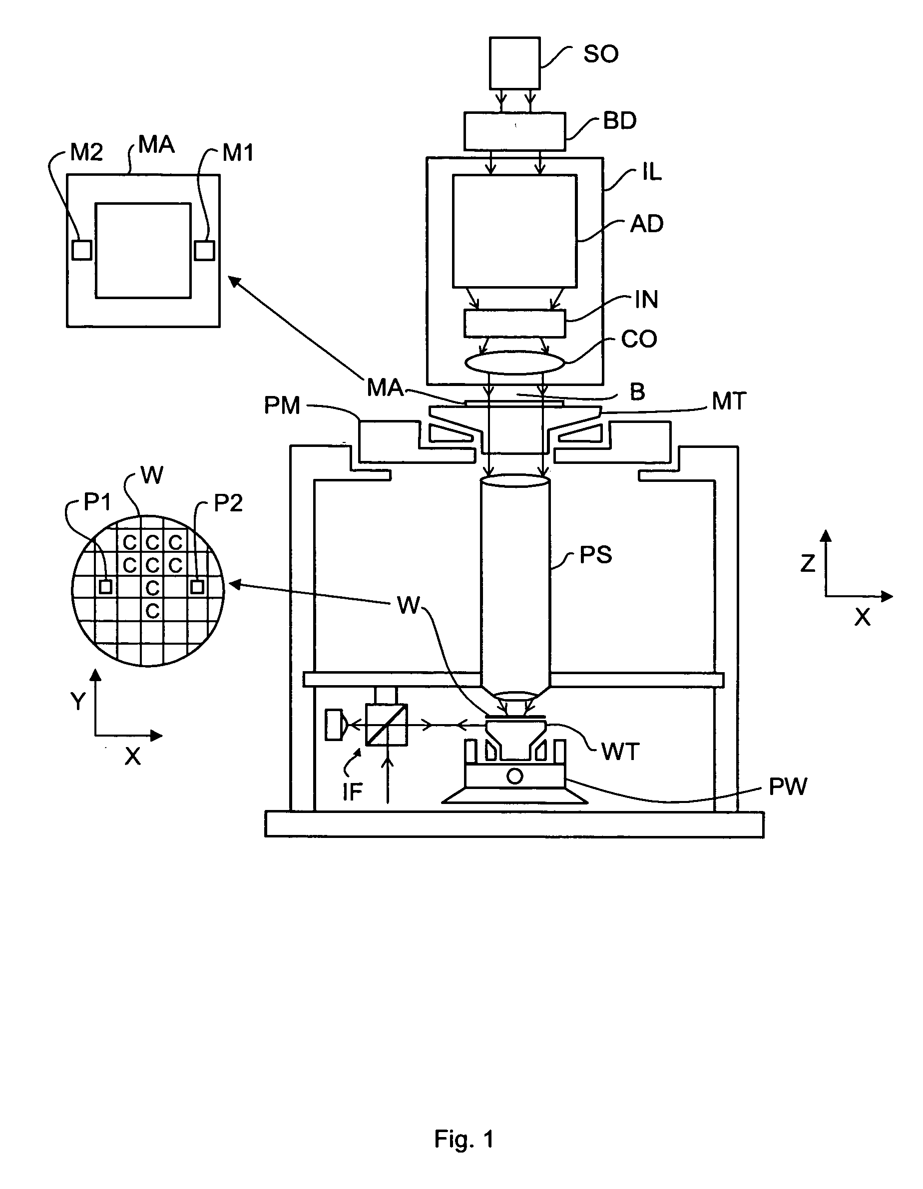
[0050]FIG. 1 schematically depicts a lithographic apparatus according to one embodiment of the invention. The apparatus includes an illumination system (illuminator) IL configured to condition a radiation beam B (e.g. UV radiation or EUV radiation) and a support structure (e.g. a mask table) MT configured to support a patterning device (e.g. a mask) MA and connected to a first positioning device PM configured to accurately position the patterning device in accordance with certain parameters. The apparatus also includes a substrate table (e.g. a wafer table) WT configured to hold a substrate (e.g. a resist-coated wafer) W and connected to a second positioning device PW configured to accurately position the substrate in accordance with certain parameters and a projection system (e.g. a refractive projection lens system) PS configured to project a pattern imparted to the radiation beam B by patterning device MA onto a target portion C (e.g. including one or more dies) of the substrate ...


PUM


Abstract

A positioning device for positioning an object table relative to a reference frame with a drive unit including a first part connectable to the reference frame and a second part for holding the object table is described. The drive unit is constructed to displace the object table in a first direction by generating a force in the first direction on the second part, and a torque acting on the second part about an axis substantially perpendicular to the first direction such that the resulting force of the force and the torque is directed substantially through the center of gravity of the assembly including the object table and the second part.

Description

BACKGROUND [0001] 1. Field of the Invention [0002] The present invention relates to a lithographic apparatus and a positioning device, which can be used in a lithographic apparatus. [0003] 2. Description of the Related Art [0004] A lithographic apparatus is a machine that applies a desired pattern onto a substrate, usually onto a target portion of the substrate. A lithographic apparatus can be used, for example, in the manufacture of integrated circuits (ICs). In that instance, a patterning device, which is alternatively referred to as a mask or a reticle, may be used to generate a circuit pattern to be formed on an individual layer of the IC. This pattern can be transferred onto a target portion (e.g. including part of, one, or several dies) on a substrate (e.g. a silicon wafer). Transfer of the pattern is typically via imaging onto a layer of radiation-sensitive material (resist) provided on the substrate. In general, a single substrate will contain a network of adjacent target po...

Claims


Application Information

Patent Timeline
Patent Type & Authority Applications(United States)
IPC IPC(8): G03B27/58
CPCG03B27/58G03F7/70758
Inventor DAMS, JOHANNES ADRIANUS ANTONIUS THEODORUS
Owner ASML NETHERLANDS BV
Why Eureka
Try Eureka