Calibration methods for tunable lasers

a laser and tunable technology, applied in the field of optical communication systems, can solve problems such as small channel separation

Inactive Publication Date: 2006-04-06
INTEL CORP
View PDF3 Cites 31 Cited by
  • Summary
  • Abstract
  • Description
  • Claims
  • Application Information

AI Technical Summary

Problems solved by technology

Greater bandwidth requirements will likely result in smaller channel separation in the future.

Method used


Image

  • Calibration methods for tunable lasers
  • Calibration methods for tunable lasers
  • Calibration methods for tunable lasers

Examples


Embodiment Construction

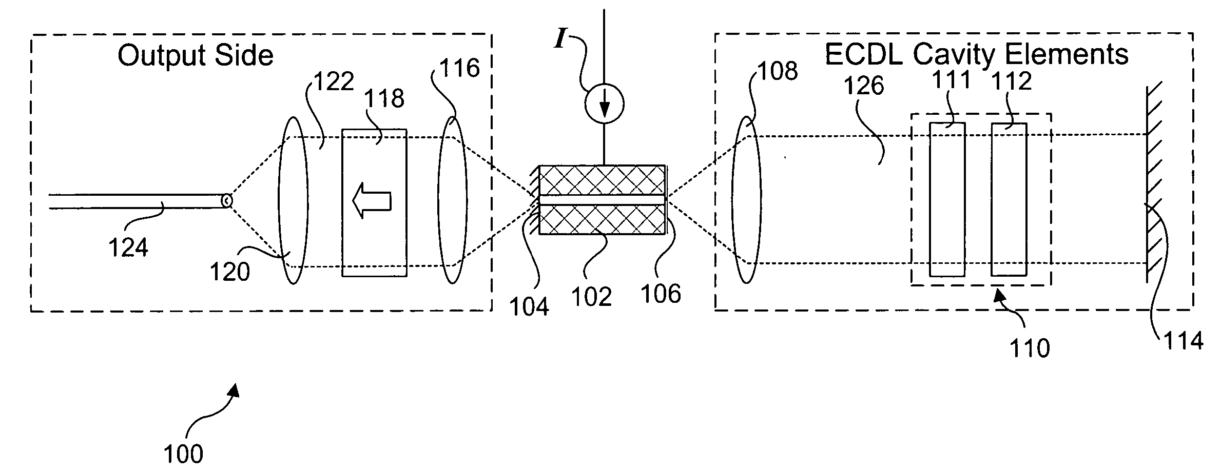
[0023] Embodiments of methods for calibrating tunable lasers are described herein. In the following description, numerous specific details are set forth to provide a thorough understanding of embodiments of the invention. One skilled in the relevant art will recognize, however, that the invention can be practiced without one or more of the specific details, or with other methods, components, materials, etc. In other instances, well-known structures, materials, or operations are not shown or described in detail to avoid obscuring aspects of the invention.

[0024] Reference throughout this specification to “one embodiment” or “an embodiment” means that a particular feature, structure, or characteristic described in connection with the embodiment is included in at least one embodiment of the present invention. Thus, the appearances of the phrases “in one embodiment” or “in an embodiment” in various places throughout this specification are not necessarily all referring to the same embodi...


PUM


Abstract

Methods for calibrating tunable lasers. Various operational characteristics of a tunable laser, such as an external cavity diode laser (ECDL), are modeled using corresponding modeling equations. Corresponding calibration processes are performed for each operational characteristics to derive parameters corresponding to each modeling equation. In one embodiment, the calibration processes relate to calibration of resistive thermal devices (RTDs), wavelength calibration, power vs. gain medium current (PI) curve calibration, and output power calibrations. The corresponding parameters that are derived from the calibration processes are stored on-board the tunable laser. During laser operations, firmware instructions are executed to perform tuning functions employing the stored parameters.

Description

FIELD OF THE INVENTION [0001] The field of invention relates generally to optical communication systems and, more specifically but not exclusively relates to enhanced tunable lasers and methods for calibrating tuning characteristics of such tunable lasers. BACKGROUND INFORMATION [0002] There is an increasing demand for tunable lasers for test and measurement uses, wavelength characterization of optical components, fiberoptic networks and other applications. In dense wavelength division multiplexing (DWDM) fiberoptic systems, multiple separate data streams propagate concurrently in a single optical fiber, with each data stream created by the modulated output of a laser at a specific channel frequency or wavelength. Presently, channel separations of approximately 0.4 nanometers in wavelength, or about 50 GHz are achievable, which allows up to 128 channels to be carried by a single fiber within the bandwidth range of currently available fibers and fiber amplifiers. Greater bandwidth re...

Claims


Application Information

Patent Timeline
Patent Type & Authority Applications(United States)
IPC IPC(8): H01S3/10H01S3/13
CPCH01S5/06H01S5/0612H01S5/065H01S5/0683H01S5/0687H01S5/141
Inventor DAIBER, ANDREW J.
Owner INTEL CORP
Why Eureka
Try Eureka