Method of and system for stabilizing high voltage power supply voltages in multi-energy computed tomography

a computed tomography and power supply voltage technology, applied in the direction of material analysis using wave/particle radiation, instruments, nuclear engineering, etc., can solve the problems of plastic explosives, baggage scanning systems may be particularly difficult to detect, plastic explosives may be formed into geometric shapes that are difficult to detect,

a computed tomography and power supply voltage technology, applied in the direction of material analysis using wave/particle radiation, instruments, nuclear engineering, etc., can solve the problems of plastic explosives, baggage scanning systems may be particularly difficult to detect, plastic explosives may be formed into geometric shapes that are difficult to detect,

US20060072703A1Inactive Publication Date: 2006-04-06ANLOGIC CORP (US)

Image

  • Method of and system for stabilizing high voltage power supply voltages in multi-energy computed tomography
  • Method of and system for stabilizing high voltage power supply voltages in multi-energy computed tomography
  • Method of and system for stabilizing high voltage power supply voltages in multi-energy computed tomography

Examples


Embodiment Construction

I. Feedback Control of HVPS Voltages

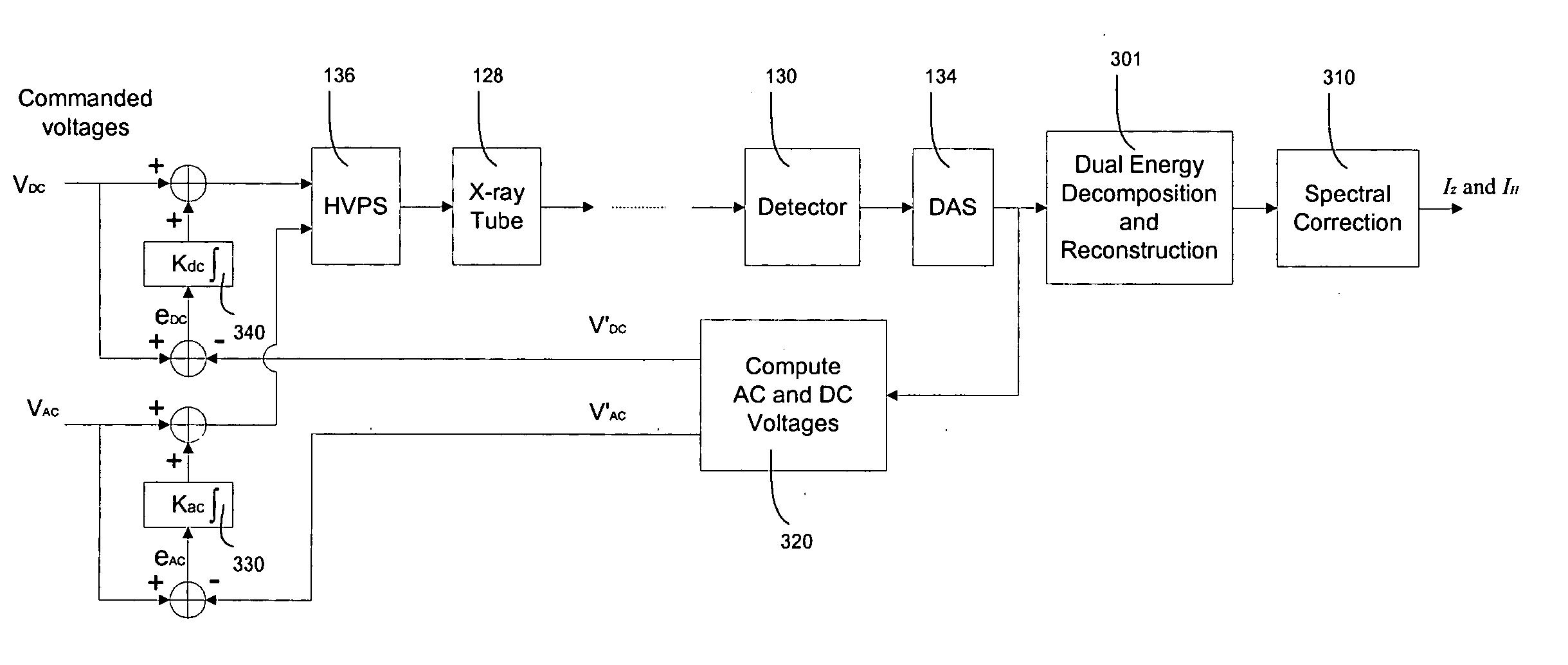
[0084] In accordance with the present disclosure, a preferred algorithm for stabilizing HVPS output voltages for dual-energy CT scanners is provided. The X-ray tube generates beam(s) of the high-energy and low-energy X-ray spectra, which are determined by the DC (Direct Current) and AC (Alternating Current) voltages supplied by the HVPS (High Voltage Power Supply) to the X-ray tube. The HVPS produces the following voltage,

V=VDC+VAC sin(2πft)

[0085] wherein VDC is the DC voltage, VAC is the AC voltage (more accurately the magnitude of the AC voltage, but for simplification the AC voltage is hereinafter referred to as VAC), and f is the frequency of the AC voltage, the latter being equal to the product of the disk rotational speed and number of views per rotation. The DC voltage and AC voltage are optimally chosen so that the reconstructed Z image yields the highest SNR (Signal to Noise Ratio). For example, in the assignee's commercial scanner syst...


PUM


Abstract

A method of and a system for stabilizing High Voltage Power Supply (HVPS) DC and AC voltages in multi-energy X-ray computed tomography scanners are provided. The method comprises generating filter ratios, computing DC and AC voltages, and feeding back the computed DC and AC voltages to the commanded voltages. The filtered ratios including an air ratio and a copper ratio are modeled as nonlinear functions of the DC and AC voltages. Computing DC and AC voltages include computing an m-ratio and an n-ratio. The parameters of the nonlinear model comprise an exponent parameter and a set of polynomial coefficients. The parameters are determined by a calibration procedure, which performs scanning at different combination of DC and AC voltages. The optimal parameters are obtained through a nonlinear least square minimization, which is solved through a brute force search over the exponent parameter and a closed form solution of the polynomial coefficients. Feeding back the computed DC and AC voltages include comparing the computed voltages with commanded voltages, integrating the difference between the computed voltages and commanded voltages, and adding the integrated voltage differences to the commanded voltages.

Description

RELATED APPLICATIONS [0001] This patent application and / or patents are related to the following co-pending U.S. applications and / or issued U.S. patents, of the assignee as the present application, the contents of which are incorporated herein in their entirety by reference: [0002]“Nutating Slice CT Image Reconstruction Apparatus and Method,” invented by Gregory L. Larson, et al., U.S. application Ser. No. 08 / 831,558, filed on Apr. 9, 1997, now U.S. Pat. No. 5,802,134, issued on Sep. 1, 1998; [0003]“Computed Tomography Scanner Drive System and Bearing,” invented by Andrew P. Tybinkowski, et al., U.S. application Ser. No. 08 / 948,930, filed on Oct. 10, 1997, now U.S. Pat. No. 5,982,844, issued on Nov. 9, 1999; [0004]“Air Calibration Scan for Computed Tomography Scanner with Obstructing Objects,” invented by David A. Schafer, et al., U.S. application Ser. No. 08 / 948,937, filed on Oct. 10, 1997, now U.S. Pat. No. 5,949,842, issued on Sep. 7, 1999; [0005]“Computed Tomography Scanning Appa...

Claims


Application Information

Patent Timeline
06 Apr 2006
Publication
US20060072703A1
IPC
H05G1/10
CPC
G01V5/0008; H05G1/10; G01V5/20
Inventors
NAIDU, RAM; YING, ZHENGRONG