Optical fiber mechanical splice with strain relief mechanism

a technology of optical fiber and mechanical splicing, which is applied in the field of members, can solve the problems of splicing with the use of the existing splicing tool as it stands, damage to the optical fiber, and possible loss of optical fiber by micro-bending, and achieves the effect of simple structur

Inactive Publication Date: 2006-04-06
CORNING RES & DEV CORP
View PDF13 Cites 29 Cited by
  • Summary
  • Abstract
  • Description
  • Claims
  • Application Information

AI Technical Summary

Benefits of technology

[0007] The present invention is devised to solve one or more of the above problems, and has for an object to provide an optical fiber splicing member which ...

Problems solved by technology

In other words, if the optical fiber extending from the element 11 is twisted or applied tension, the optical fiber is damaged or subject to loss by micro-bending.
If the holding force of the clip member 17 is too large, the extension/contraction of the optical fiber in the axis direction by an environmental temperature...

Method used


Image

  • Optical fiber mechanical splice with strain relief mechanism
  • Optical fiber mechanical splice with strain relief mechanism
  • Optical fiber mechanical splice with strain relief mechanism

Examples


Embodiment Construction

[0039] An optical fiber splicing member and a method for splicing optical fibers which is carried out with the use of the splicing member as an embodiment of the present invention will be described below with reference to the drawings throughout which like parts are designated by like reference numerals.

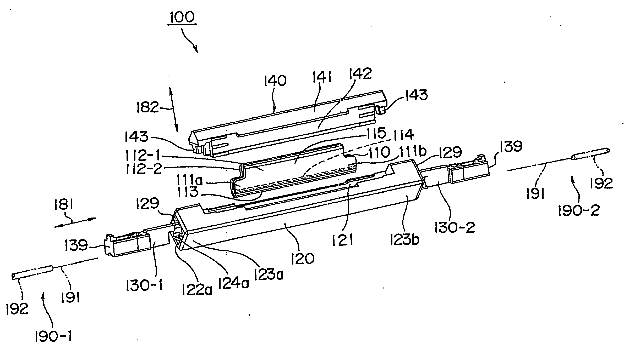
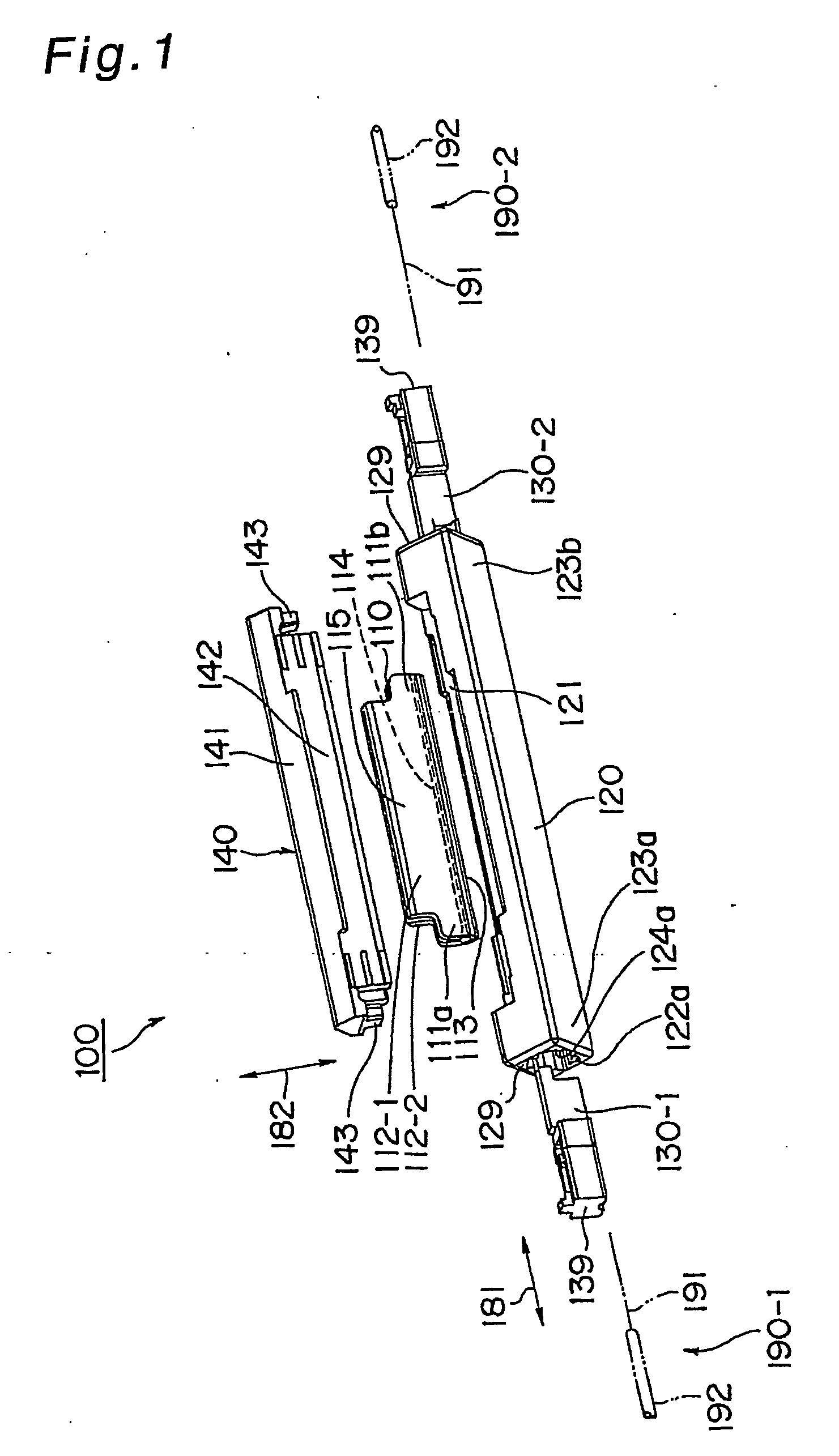
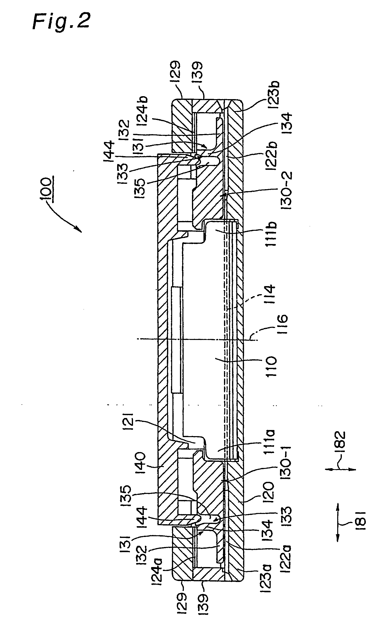
[0040] As shown in FIGS. 1 and 2, the optical fiber splicing member 100 is provided with a joint element 110, a jacket 120, two end plugs 130 and a cap 140. Optical fibers 190-1 and 190-2 (generally referred to as “an optical fiber 190” in some cases) are inserted from the side of both ends of the optical fiber splicing member 100 as shown in the drawings when splicing the optical fibers 190. The optical fiber 190 in the embodiment is constituted of a bare fiber 191 formed of a glass material, and a buffer coating 192 for coating the bare fiber 191. In splicing the optical fibers by the optical fiber splicing member 100, the buffer coating 192 of each optical fiber 190 is removed be...


PUM


Abstract

To provide an optical fiber splicing member which can hold optical fiber buffer coatings stably in a simple structure as compared with conventional art, and which enables use of an existing splicing tool. There are provided a joint element (110), a jacket (120), buffer retainers (131) and a cap (140). By setting and pressing the cap to the jacket, it becomes possible to splice bare fibers of optical fibers (190) with each other by the joint element and to press the buffer coatings (192) by the buffer retainers. Assembling the splicing member is thus facilitated while the existing optical fiber splicing tool is utilizable as it is. The buffer coatings can be held stably because the holding is achieved through the pressing.

Description

TECHNICAL FIELD [0001] The present invention relates to a member for splicing optical fibers by a mechanical pressure fixing system. BACKGROUND OF THE INVENTION [0002] In one method for splicing ends of optical fibers, there is a mechanical splicing system whereby ends of bare fibers of optical fibers are butted and mechanically fixed to each other with pressure. Ends of the optical fibers to be spliced are butted against each other and fixed with pressure inside a pressing fixing member equipped to a splice as a member for splicing the optical fibers. More specifically, the splice 10 shown in FIG. 15 includes the element 11, a jacket 12 for storing the element 11, end plugs 13-1 and 13-2 each of which has an optical fiber insertion opening 13a and can be fitted in an end of the jacket 12 for guiding the optical fiber, and a cap 14. The element 11 as a V-shaped foldable member holds the bare fibers of the optical fibers inserted from both ends thereof in a state in which both ends o...

Claims


Application Information

Patent Timeline
IPC IPC(8): G02B6/255C03B37/00
CPCG02B6/3802G02B6/3806G02B6/3887G02B6/3888
Inventor YAMAUCHI, TAKAYAYAZAKI, AKIHIKO
Owner CORNING RES & DEV CORP
Why Eureka
Try Eureka