Loose tube optical cable

a technology of optical cable and loose tube, which is applied in the direction of bundled fibre light guide, instruments, fibre mechanical structures, etc., can solve the problems of deteriorating the characteristics of optical fibers mounted in loose tubes, difficult to arrange a regular three-dimensional twist in a longitudinal direction, and inapplicable technology, etc., to achieve the effect of reducing the diameter and weight of optical cables

Inactive Publication Date: 2006-04-06
LG CABLE INC
View PDF6 Cites 34 Cited by
  • Summary
  • Abstract
  • Description
  • Claims
  • Application Information

AI Technical Summary

Benefits of technology

[0009] The present invention is designed to solve the problems of the prior art, and therefore an object of the present invention is to provide a loose tube optical cable having an improved structure which may have the same number of loose tube optical fiber units as the conventional 1+5 or 1+6 structure together with reduced optical cable diameter and weight, minimize an effect influenced on the loose tube optical fiber unit due to the optical cable tensile member, and satisfy a tensile force condition of the optical cable.

Problems solved by technology

However, such a technical configuration may be not applicable if the tube of the optical fiber unit is made of plastic.
This may deteriorate the characteristics of the optical fibers mounted in the loose tube and make it harder to arrange a regular three-dimensional twist in a longitudinal direction.
In addition, in such a configuration, it is not easy to control the tension of the optical cable during the installation procedure, thereby deteriorating its workability.
Thus, when using the FRP, it is hard to keep a twisted state of the aggregation composed of the tensile member and the loose tube optical fiber units, and the aggregation is not normally twisted if a twisting pitch is not long.
However in this case, a tensile stress is caused to the aggregation, which may deteriorate the signal characteristics during the optical signal transmission or damage the loose tube itself.
On the other hand, if the twisting pitch is increased when twisting the tensile member and the optical fiber units having the tube made of plastic, the tensile window is decreased, thereby causing a problem in the temperature characteristics of the optical cable.
Thus, it also should be considered that there are problems in the cable design in which factors of the optical fiber unit such as EFL (Excess Fiber Length) and the loose tube diameter should be strictly selected.

Method used


Image

  • Loose tube optical cable
  • Loose tube optical cable
  • Loose tube optical cable

Examples


first embodiment

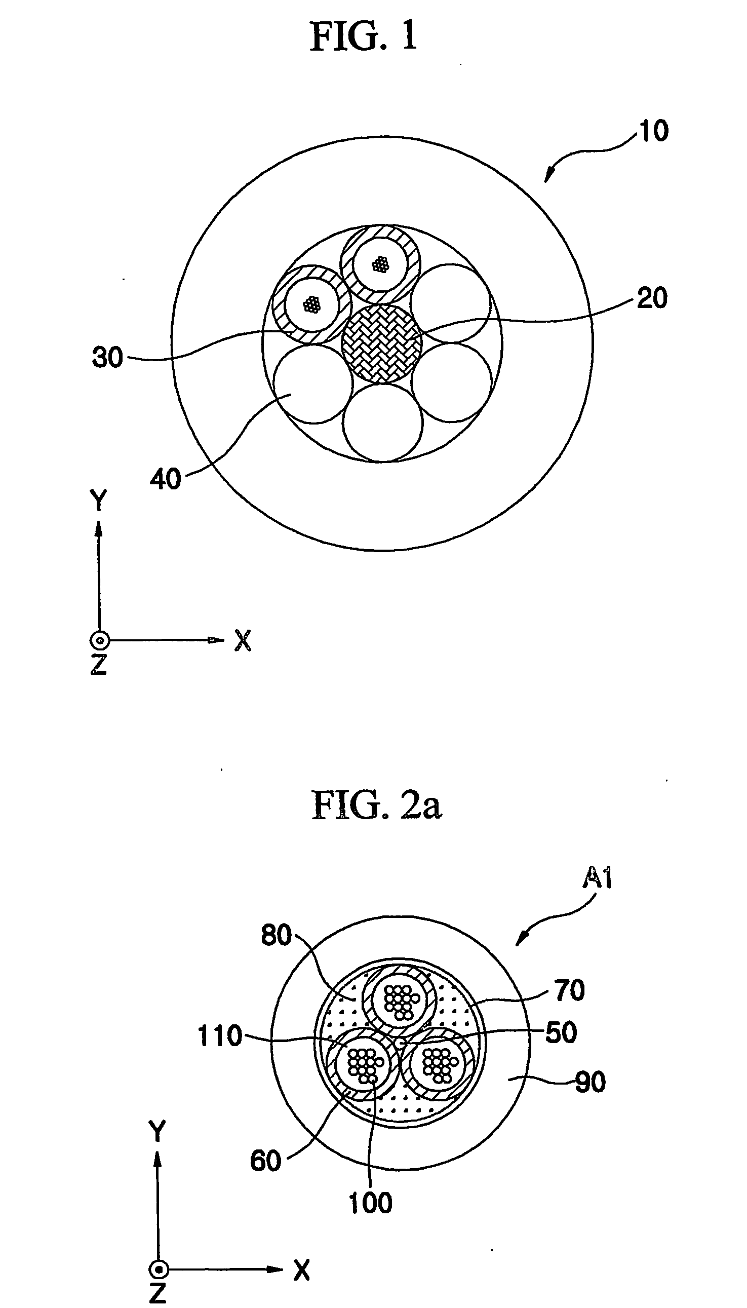
[0027]FIGS. 2a and 2b are sectional views respectively showing loose tube optical cables having 1+3 structure and 1+4 structure according to the present invention.

[0028] Referring to FIGS. 2a and 2b, the loose tube optical cable A1 and B1 has a central tensile member 50 longitudinally extended at the center of the optical cable A1 and B1, a plurality of cable aggregation units composed of three or four optical fiber units 60 longitudinally twisted on the outer circumference of the central tensile member 50 in 1+3 structure or 1+4 structure, a fibered tension-reinforcing member 80 for surrounding a cable core aggregation 70 including the central tensile member 50 and the optical fiber units 60, and a cable coating 90 for surrounding the cable core aggregation 70 surrounded by the fibered tension-reinforcing member 80 in a longitudinal direction. Here, the term ‘cable aggregation unit’ is commonly defined as a cylindrical aggregation unit longitudinally twisted and extended on the out...

second embodiment

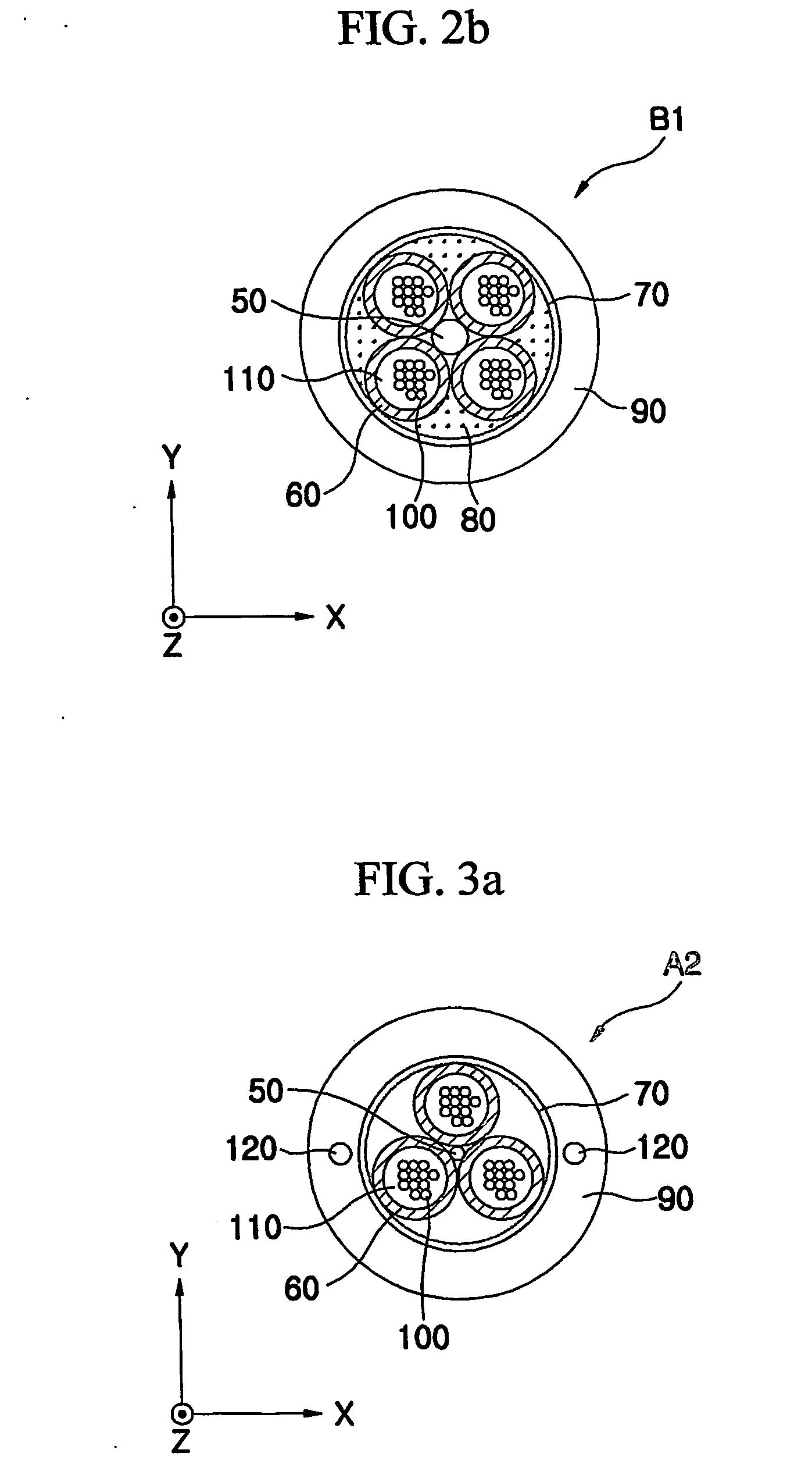
[0035]FIGS. 3a and 3b are sectional views showing a loose tube optical cable of 1+3 structure or 1+4 structure according to the present invention.

[0036] Referring to FIGS. 3a and 3b, the loose tube optical cable A2 and B2 according to the second embodiment of the present invention is provided with wired tension-reinforcing members 120 formed in the cable coating 90 in opposite positions substantially as much as 180° and extended in a longitudinal direction, instead of the above-mentioned fibered tension-reinforcing member 80 (see FIGS. 2a and 2b) of the first embodiment. In the second embodiment of the present invention, a plurality of cable aggregation units are the loose tube optical fiber units 60 longitudinally twisted and extended on the outer circumference of the central tensile member 50.

[0037] The wired tension-reinforcing members 120 are preferably provided in point symmetry for the central tensile member 50 in order to efficiently disperse the tensile stress applied to th...

third embodiment

[0041]FIGS. 4a and 4b are sectional views showing a loose tube optical cable of 1+3 structure or 1+4 structure according to the present invention.

[0042] Referring to FIGS. 4a and 4b, the loose tube optical cable A3 and B3 according to the third embodiment of the present invention is provided with a fibered ring-shaped tension-reinforcing member 130 formed in the cable coating 90 and extended substantially coaxially with the central tensile member 50, instead of the above-mentioned fibered tension-reinforcing member 80 (see FIGS. 2a and 2b) of the first embodiment. In the third embodiment of the present invention, a plurality of cable aggregation units are the loose tube optical fiber units 60 longitudinally twisted and extended on the outer circumference of the central tensile member 50.

[0043] The ring-shaped tension-reinforcing member 130 is preferably provided in point symmetry for the central tensile member 50 in order to efficiently disperse the tensile stress applied to the op...


PUM


Abstract

Disclosed is a loose tube optical cable, which includes at most four cable aggregation units longitudinally twisted in contact with a central tensile member and having a loose tube optical fiber unit or inclusion, a cable coating for longitudinally surrounding a cable core aggregation having the central tensile member and the cable aggregation units, and one selected from the group consisting of a fibered tension-reinforcing member for surrounding the cable core aggregation, a wired tension-reinforcing member and a ring-shaped tension-reinforcing member formed in the cable coating. This loose tube optical cable has a compact structure by excluding unnecessary inclusion, thereby decreasing the outer diameter and the weight thereof. In addition, since the central tensile member and the tension-reinforcing member are not twisted with the cable aggregation units, tensile stress may be minimized in the optical cable.

Description

TECHNICAL FIELD [0001] The present invention relates to a loose tube optical cable, and more particularly to a loose tube optical cable having a more compact structure for reducing an outer diameter and a weight of the optical cable together with satisfying a tensile force requirement of the optical cable. BACKGROUND ART [0002] The loose tube optical cable is generally configured so that a plurality of optical fiber units in which the required number of optical fibers are mounted in a plastic tube together with jelly compound (hereinafter, referred to as ‘loose tube optical fiber unit’) are aggregated around a tensile strength member positioned at the center of the cable. At this time, a plurality of the loose tube optical fiber units are aggregated around the tensile strength member in a helical twist or SZ twist in order to minimize the stress caused to the optical fiber by the bending of the optical cable when the optical cable is installed or taken up around a drum. [0003] The c...

Claims


Application Information

Patent Timeline
Patent Type & Authority Applications(United States)
IPC IPC(8): G02B6/04G02B6/44
CPCG02B6/441G02B6/4432G02B6/4433G02B6/44
Inventor KIM, TAE-GYOUNGSON, MIN
Owner LG CABLE INC
Why Eureka
Try Eureka