Test device and method for testing a rail car brake system

a brake system and test device technology, applied in hydrodynamic testing, instruments, force/torque/work measurement, etc., can solve the problems of additional skilled labor, increased opportunity for operator error in implementing any programming change, and variable errors in the test of the brake system

Inactive Publication Date: 2006-04-06
GRAHAM WHITE MANUVACTURING +1
View PDF2 Cites 21 Cited by
  • Summary
  • Abstract
  • Description
  • Claims
  • Application Information

AI Technical Summary

Benefits of technology

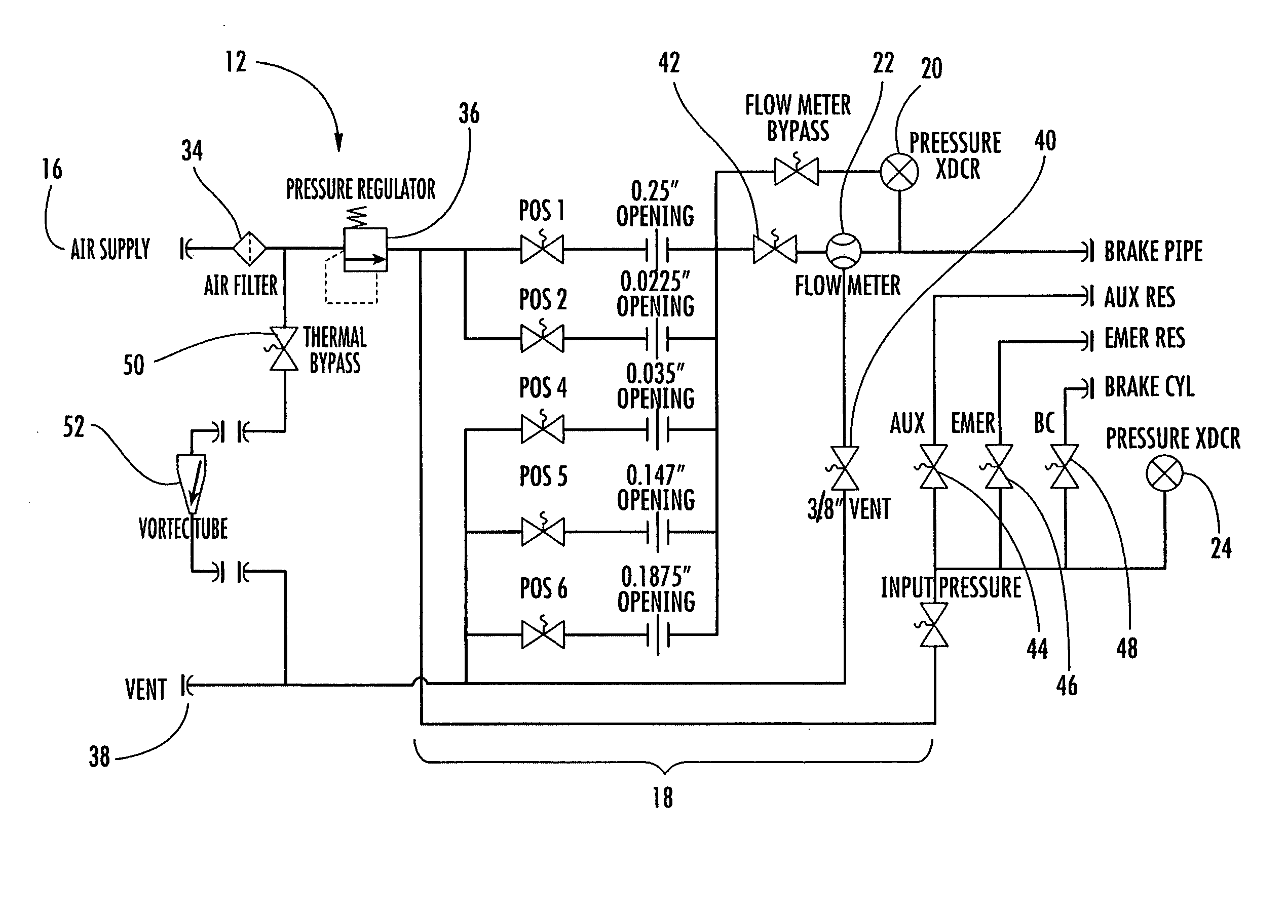
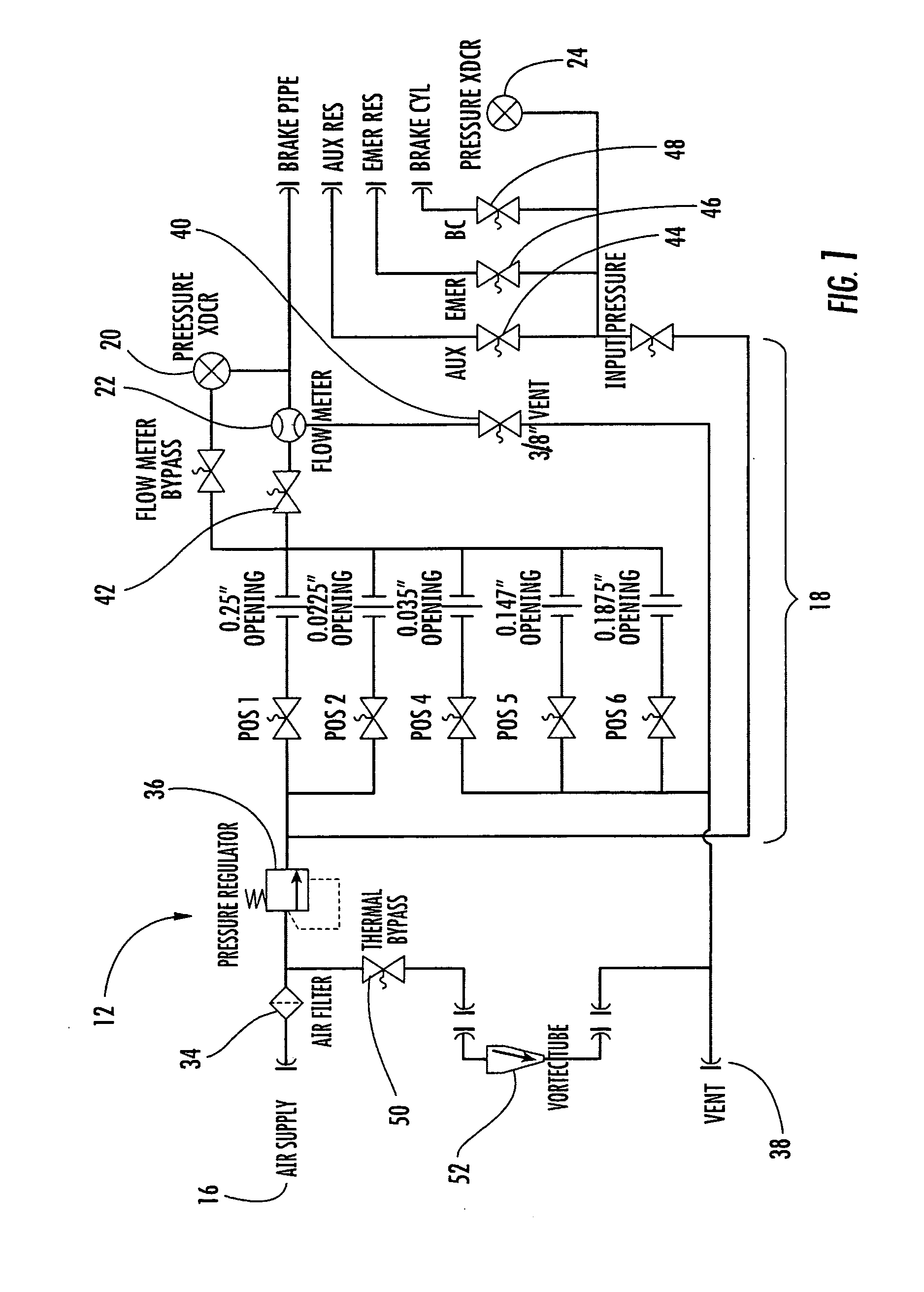
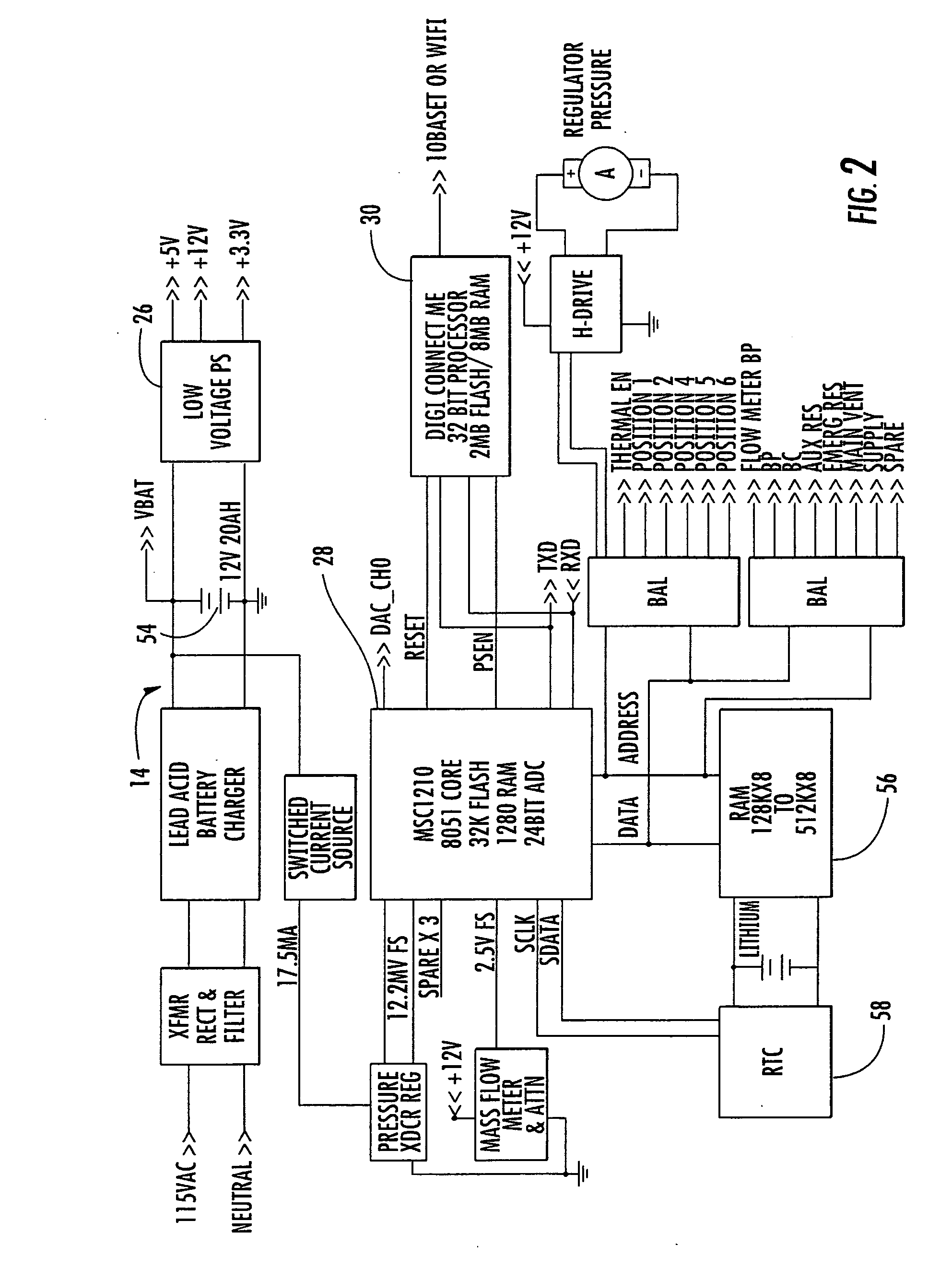
[0009] In one embodiment of the present invention, a test device for testing a rail car brake system includes an air supply, a valve manifold, a control circuit, a power supply, and a web server interface. The air supply provides test air to the rail car brake system being tested. The valve manifold connects between the air supply and the rail car brake system, and the valve manifold includes a valve for selectively supplying and venting the test air to or from the rail car brake system and a sensor for measuring the test air. The control circuit operatively connects with the valve manifold for selectively positioning the valve and recording a measurement from the sensor. The power supply connects to the control circuit for providing electrical power to the control circuit. The web server interface is in communication with the control circuit. The web server interface is configured to receive programming instructions from a predetermined web page and to communicate the programming instructions to the control circuit for testing the rail car brake system.
[0010] In particular embodiments, the valve manifold may further include a solenoid operated valve that is positioned by the control circuit. Furthermore, the valve manifold may include a pressure sensor for measuring the pressure of the test air and / or a flow sensor for measuring the flow rate of the test air. In still further embodiments, the valve manifold may include a thermal bypass valve for diverting a portion of the test air for selectively heating or cooling the rail car brake system test device.
[0011] In other particular embodiments, the web server interface may be configured to receive data from the control circuit and to communicate the data to a location external to the test device. The test device may further include a data entry device for communicating with the control circuit and / or a web browser for accessing the predetermined web page.
[0012] In another embodiment of the present invention, the web server interface is configured to receive programming instructions from a source external to the rail car brake system test device and to communicate the programming instructions to the control circuit for testing the rail car brake system. The source external to the rail car brake system test device may be a microprocessor, a predetermined web page, or other source having the programming instructions.
[0013] The present invention further includes a method for testing a rail car brake system using a test device. The method includes connecting a supply of test air to a valve manifold and connecting the valve manifold to the rail car brake system. A control circuit is operatively connected to the valve manifold, and programming instructions are retrieved from a predetermined web page. The programming instructions are communicated to the control circuit, and the control circuit executes the programming instructions to selectively position the valve manifold according to the programming instructions and measure the test air.

Problems solved by technology

As a result, various errors can occur in the brake system test due to operator error.
This individual action causes delays in subsequent brake tests, requires additional skilled labor sufficiently knowledgeable to perform the reprogramming, and create an additional opportunity for operator error in effecting any programming changes.

Method used


Image

  • Test device and method for testing a rail car brake system
  • Test device and method for testing a rail car brake system
  • Test device and method for testing a rail car brake system

Examples


Embodiment Construction

[0022] Reference will now be made in detail to present embodiments of the invention, one or more examples of which are illustrated in the accompanying drawings. Each example is provided by way of explanation of the invention, not limitation of the invention. In fact, it will be apparent to those skilled in the art that modifications and variations can be made in the present invention without departing from the scope or spirit thereof. For instance, features illustrated or described as part of one embodiment may be used on another embodiment to yield a still further embodiment. Thus, it is intended that the present invention covers such modifications and variations as come within the scope of the appended claims and their equivalents.

[0023] The present invention relates generally to a test device 10 and method for testing a rail car brake system. The test device 10 generally includes a pneumatic circuit 12 and an electrical circuit 14. The pneumatic circuit 12 connects a supply of t...


PUM


Abstract

The present invention discloses and claims a test device and method for testing a rail car brake system. The test device includes a pneumatic circuit and electronic circuit connecting a supply of test air to the rail car brake system being tested. The pneumatic and electronic circuits operate to selectively supply and vent the test air to or from the rail car brake system according to programmed instructions. The test device further includes a web server interface for communicating with a predetermined web page or other source external to the rail car brake system test device to retrieve and download additional programming instructions.

Description

BACKGROUND OF THE INVENTION [0001] Railway trains and cars typically include a pneumatic brake system. The brake system is critical to the safe operation of the rail cars and is therefore subject to periodic testing to ensure the integrity and satisfactory performance of the brake system. The present invention provides a test device and method for testing the brake system on a rail car. [0002] In the United States, the Association of American Railroads (AAR), in conjunction with the Federal Railway Administration, has promulgated and adopted a Manual of Standards and Recommended Practices. Included in this manual is Standard S-486 for testing the brake system on a rail car. In general, Standard S-486 includes a series of tests that measure the pressure and flow rate of the air in the brake system under various conditions. These pressure and flow rate measurements are then used to verify that the brake system has sufficient physical integrity and will perform satisfactorily under exp...

Claims


Application Information

Patent Timeline
Patent Type & Authority Applications(United States)
IPC IPC(8): G06F19/00
CPCB60T17/228
Inventor CRANE, JERRY D.EDWARDS, SCOTT G.EDWARDS, KATHRYN M.GRANGER, ALAN R.MASEK, WILLIAM E.
Owner GRAHAM WHITE MANUVACTURING
Why Eureka
Try Eureka