

Refill for correction pen and refill unit
a technology for refilling units and correction pen refills, which is applied in the direction of nibs, application, erasers, etc., can solve the problems of insufficient transparency, inability to accurately monitor the remaining amount, and difficulty in completely consuming the charged correction fluid
Inactive Publication Date: 2006-04-13
MITSUBISHI PENCIL CO LTD
View PDF5 Cites 9 Cited by
- Summary
- Abstract
- Description
- Claims
- Application Information
AI Technical Summary
Benefits of technology
[0012] Under consideration of the problems of the conventional refill and refill unit for a correction pen and in order to solve them, the present inventors have found that a refill for a correction pen of the above first object can be obtained by constructing a refill for a correction pen that stores a correction fluid having at least methyl cyclohexane as the main solvent, of an molded articles of a resin having specific physical properties, and thus have completed a refill for a correction pen of the present invention. The present inventors also
Problems solved by technology
Molded articles of polyamide resin made from aliphatic monomers, such as nylon 12 and the like, described in these literatures, have solvent resistance, however do not have high enough transparency.
Further, the correction fluid tends to adhere to the inner wall surface of the container and does not flow down as the correction fluid is consumed with application, so there are still problems in that the remaining amount cannot be correctly monitored and that it is difficult to use up the charged correction fluid completely.
Such a stress and an additional stress which may arise in the ballpoint pen tip during writing or application, in combination, would cause reduction of the press-fitting force on the tip holder or tip with the passage of time, leading to problems such as easy drop-off of the tip holder or tip and liability to ink leaking from the press fitting part.
However, the above configuration on its own, in which the front part of the barrel to which the rear end of the tip holder is press fitted is covered over its outer peripheral surface with a metal tube, cannot be expected to exert a sufficient effect, hence in the above publication the covering metal tube is adapted to be held between a flange of the tip holder and the front end of the barrel to achieve the expected effect.
Further, because of use of the tip holder, parts increase in number, resulting in problems in view of processing accuracy and assembly precision.
Moreover, in a refill unit which has a tip directly press fitted to a synthetic resin-made ink reservoir and is mounted to a ballpoint type applicator whose pen tip can be projected and retracted from the front part of the barrel by a clicking mechanism and which has a pressurizing mechanism in linkage with the clicking action, an additional pressure from the rear end of the ink reservoir is further applied in combination with the internal stresses at the front part of the ink reservoir to which the tip is press fitted and stresses acting on the ballpoint tip during application, hence leading to problems of more likeliness of drop-off of the tip and leaking of correction fluid, than usual.
Method used
View moreImage
Smart ImageViewing Examples

Examples
examples
[0108] Next, the present invention shall be further described in detail with reference to the specific examples, the present invention, however, shall not be limited by the following examples.
example 1
[0110] A tube having an outer diameter of 8 mm and an inner diameter of 6 mm with a wall thickness of 1 mm was extrusion molded from Nylon MXD6 (manufactured by MITSUBISHI GAS CHEMICAL COMPANY, LTD., the same hereinbelow) to form a refill for a correction pen of 70 mm long.
example 2
[0111] A tube having an outer diameter of 8 mm and an inner diameter of 6 mm with a wall thickness of 1 mm was extrusion molded from TROGAMID T5000 (manufactured by Daicel-Huels, Ltd.) to form a refill for a correction pen of 70 mm long.
Login to View More PUM
| Property | Measurement | Unit |
|---|---|---|
| Percent by mass | aaaaa | aaaaa |
| Thickness | aaaaa | aaaaa |
| Weight | aaaaa | aaaaa |
Abstract
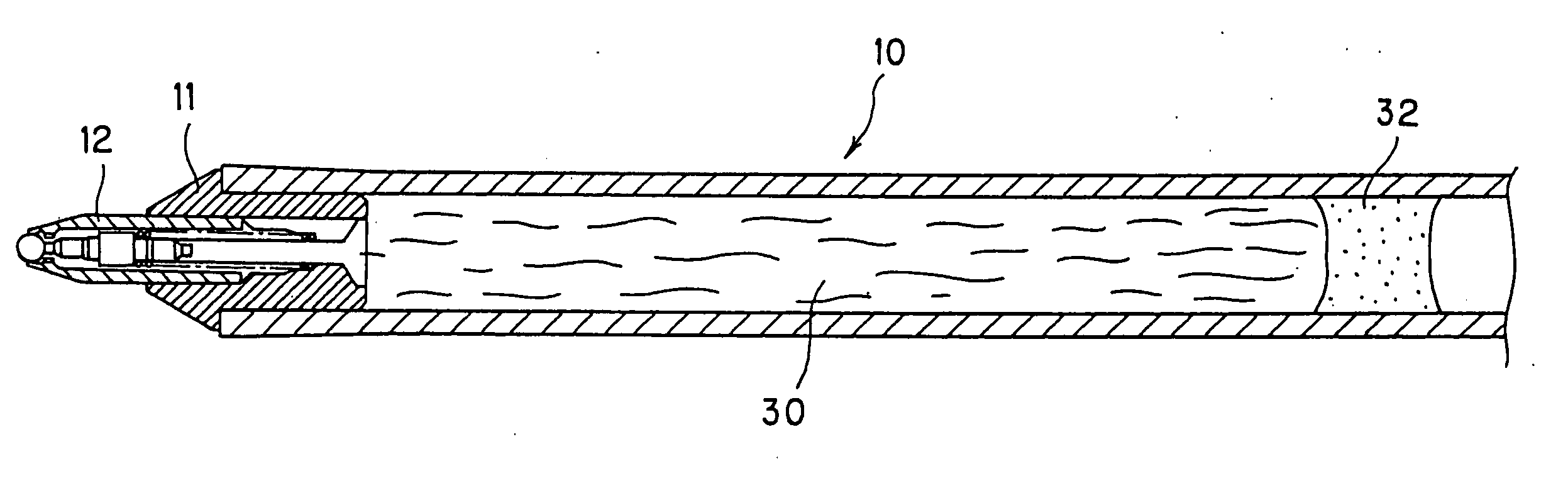
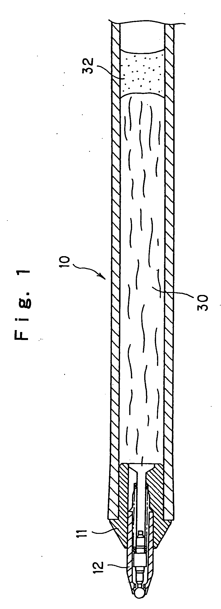
A refill for a correction pen which is excellent insolvent resistance and moldability and can make its content, i.e., a correction fluid having methyl cyclohexane as the main solvent and the remaining amount easily visible during usage and as time passes, is constructed of a molded article of a polyamide resin obtained from monomers having an aromatic ring or a naphthene ring, a molded article of a blend of two or more kinds of polyamide resins, or a molded article having a multi-layered structure of two or more layers whose innermost layer in contact with the correction fluid is constituted of a polyamide resin. The applying part of a refill unit mounted on a ballpoint type applicator having a pressurizing mechanism in linkage with clicking action is formed by press fitting the rear end of a ballpoint pen tip having a rotatable ball to the attachment portion at the front end of an ink reservoir and a metal tube is squeezed to cover the outer periphery of the attachment portion at the front end of the ink reservoir to which the tip is fitted.
Description
TECHNICAL FIELD [0001] The present invention relates to a refill for a correction pen which is excellent in transparency and visibility (clear drain ability) as well as relating to a synthetic resin-made refill unit which is mounted to an applicator such as a ballpoint type correction pen whose pen tip can be projected and retracted from the front part of the barrel by a clicking mechanism and which has a pressurizing mechanism in linkage with the clicking action. BACKGROUND ART [0002] Recently, in consideration of environmental issues, there is a demand for correction fluid containers for storing a correction fluid to be given in a so-called refillable form. To develop a correction fluid container into a refillable form, it is necessary to select a solvent resistant material because methyl cyclohexane, as the main solvent of the correction fluid, has high volatility. It is also necessary to select a material having such transparency that permits the remaining amount of the correcti...
Claims
Login to View More Application Information
Patent Timeline
 IPC IPC(8): C09D11/00B43K1/01B43K1/08B43K7/02B43K7/03B43K7/08B43K7/12B43K24/08B43L19/00B43M11/08C09D10/00C09D11/18
CPCB43K1/088B43K7/02B43K7/03B43K7/08B43K7/12B43K24/08B43L19/0018B43L19/0068B43M11/085C09D10/00C09D11/18B43K7/10B43L19/00
InventorKOBAYASHI, KYOKOONO, MAKOTOFUKAI, AKIRAKOYAMA, TAKAONAKAMURA, HITOSHIOMOTO, KEIKORIKI, TADASHI
OwnerMITSUBISHI PENCIL CO LTD