
Mask with anti-asphyxia valve

Inactive Publication Date: 2006-04-13
RESMED LTD
View PDF54 Cites 67 Cited by
  • Summary
  • Abstract
  • Description
  • Claims
  • Application Information

AI Technical Summary

Benefits of technology

[0014] It is a further aspect of the present invention to provide an improved valve of simpler construction than those prior art valves discussed above.

Problems solved by technology

Problems with prior art assemblies include:
(a) They may be inadvertently assembled without the additional components
(b) They may be incorrectly assembled, for example, incorrectly aligned
(c) During the course of treatment, the patient may inadvertently remove or dismantle the assembly and incorrectly reassemble it.
However, a problem with the known types of masks is that, because individuals vary so much from the average, the masks must be forced against their inherent resiliency to deform and so adapt to the shapes of the users in order to avoid gas leakage.
If the flow generator's operation is interrupted as a result of a power outage or other mechanical or electrical failure, there may be a significant build up of carbon dioxide in the mask as the patient's exhaled air is not washed out of outlet vents which are usually contained in the mask.
This may present a health problem to the patient.
However, this system suffers from being a fairly complicated and expensive system whose correct operation relies on a counter balanced moving part moving relative to its housing.
Further, if any condensation from the air gets on or around the balanced valve element, the operation of this valve element can be compromised.
This valve is also difficult to clean.

Method used


Image

  • Mask with anti-asphyxia valve
  • Mask with anti-asphyxia valve
  • Mask with anti-asphyxia valve

Examples


Embodiment Construction

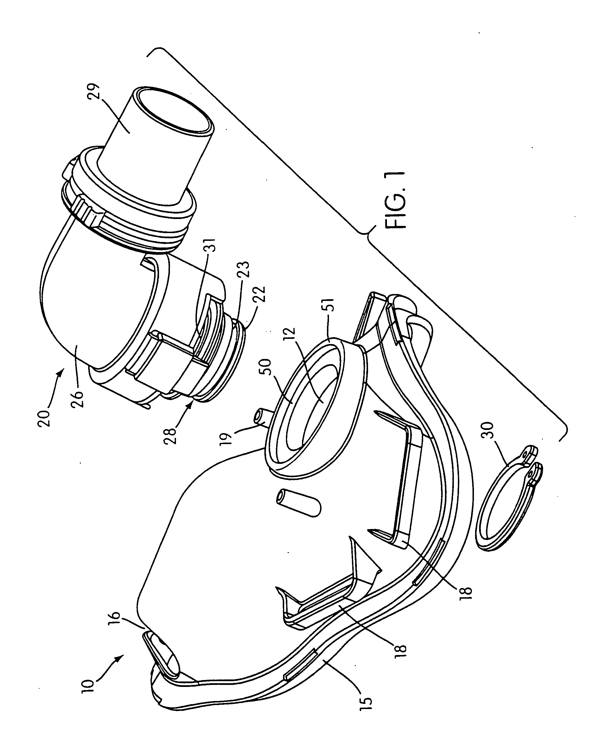
[0061] In FIG. 1 a mask frame is shown generally at 10. The mask is designed to be worn on a patient's face and is secured by means of straps (not shown) received by attachment points 18.

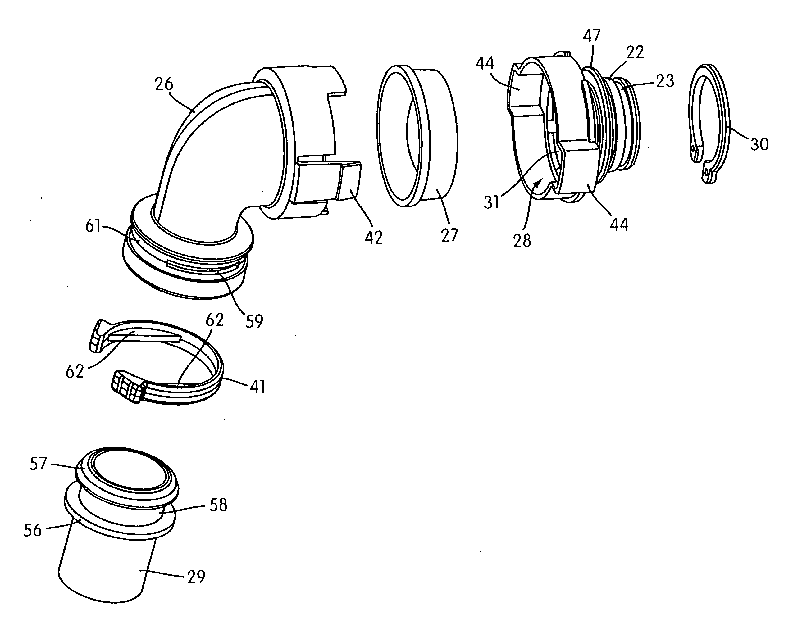
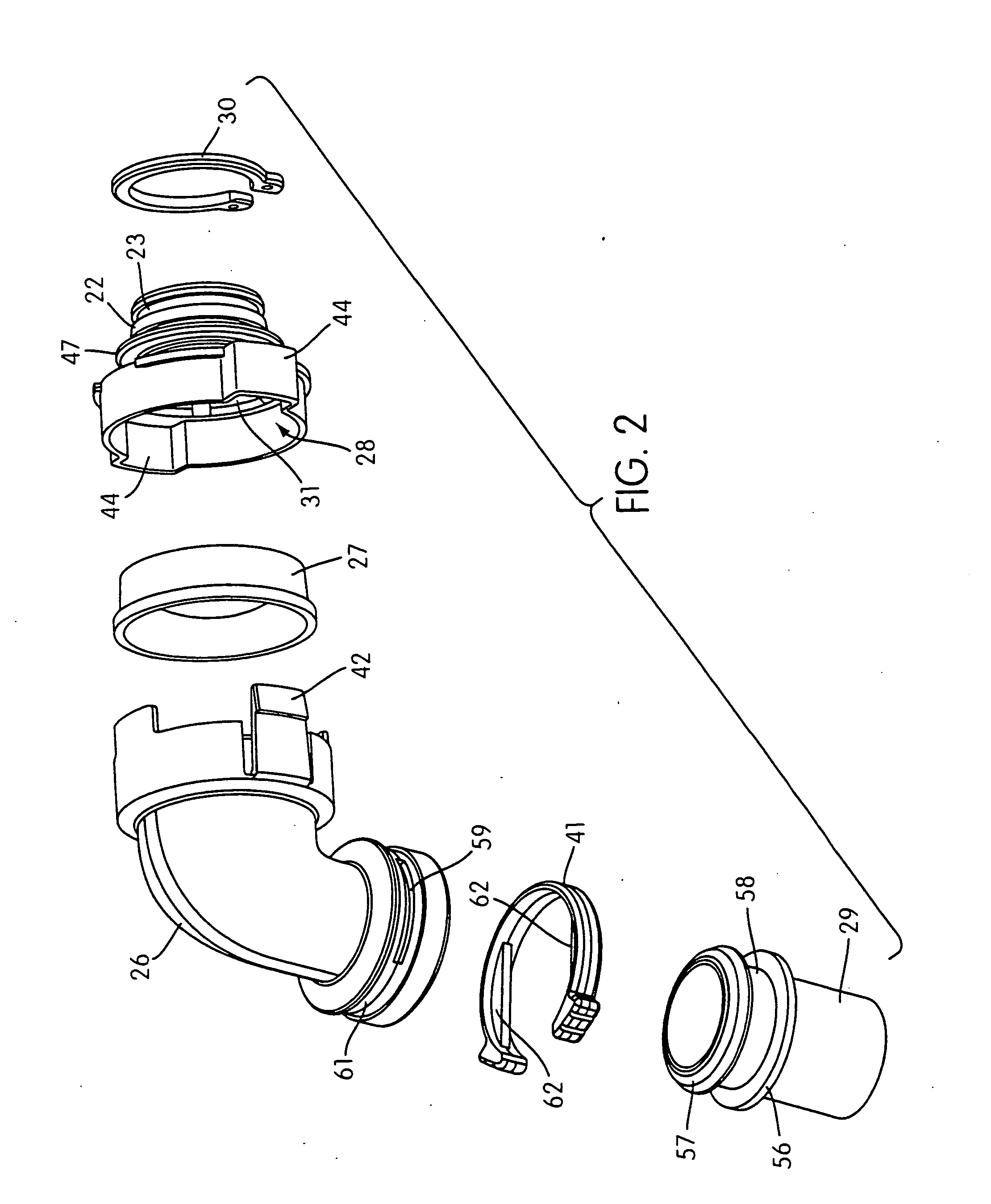
[0062] A conduit end assembly is shown generally at 20, including an elbow part 26 having at one end thereof a combined vent / connector piece 28. The elbow and vent / connector piece together form a housing for an anti-asphyxia valve (as will be further discussed) or other internal components (not shown). At the other end of the elbow is a detachable swivel tube 29 for connection of the gas delivery conduit (not shown).

[0063] The mask 10 includes a circular aperture 12 sized to receive a mating portion 22 of the vent / connector piece 28. The mating portion 22 has an annular groove 23 formed therein that receives a locking means 30 in the form of a C-shaped clip attached after mating to the mask. The clip 30 has an outside diameter greater than the width of the aperture 12 and an inner diameter adapted...


PUM


Abstract

An anti-asphyxia valve includes at least one flap having a first portion adapted for mounting to the housing and a second portion adapted to flex between a first open position allowing gas to pass from the patient side to the housing interior through the at least one port, and from the blower side through the at least one port, to atmosphere when a difference in gas pressure in the housing interior and atmosphere is below a predetermined operating threshold, and a second forcibly closed position substantially occluding the at least one port when the difference in gas pressure between the housing interior and atmosphere is substantially equal to or above the operating threshold.

Description

[0001] This is a Divisional of U.S. application Ser. No. 09 / 498,705 filed on Feb. 7, 2000, the entirety of which is hereby incorporated herein by reference.FIELD OF THE INVENTION [0002] This invention relates to improvements in patient gas delivery apparatus of the kind used in the analysis and treatment of respiratory disorders. The invention will be described with particular reference to patient gas delivery apparatus used in the treatment of respiratory disorders such as Obstructive Sleep Apnea (OSA) but it is not intended to be limited thereto. [0003] The present invention also relates to an anti-asphyxia valve. The valve has been developed primarily for use between a patient and means (e.g., a blower or respirator) to deliver a breathable gas to the patient, such as is used in the Continuous Positive Airway Pressure (CPAP) treatment of Obstructive Sleep Apnea (OSA), and will be described hereinafter with reference to this application. The valve is also suitable for use in other...

Claims


Application Information

Patent Timeline
IPC IPC(8): A62B9/02A62B23/02A61M16/06A61M16/08A61M16/20
CPCA61M16/06A61M16/0683A61M16/08A61M16/208Y10S128/912A61M16/0616A61M16/0825A61M16/085Y10T137/7771A61M16/0816A61M16/20
Inventor WALKER, ADRIENNE MARY CLAIRECRUMBLIN, GEOFFREYSMART, GREGORY S.GUNARATNAM, MICHAEL K.KWOK, PHILIP R.LITHGOW, PERRY D.
Owner RESMED LTD
Learn More