Tower-type grease removal apparatus for commercial grease trap assemblies

Inactive Publication Date: 2006-04-13
WEYMOUTH BRET M
View PDF14 Cites 4 Cited by
  • Summary
  • Abstract
  • Description
  • Claims
  • Application Information

AI Technical Summary

Benefits of technology

[0009] Another object and advantage of this invention is the provision of a skimming and grease removal apparatus of the class described which may be provided as a skimming and grease removal apparatus for retrofit installation onto existing and already-installed grease trap tank assemblies with minimal modification thereto.
[0010] Another object and advantage of this invention is the provision of a skimming and grease removal apparatus of the class described wherein the grease removal and collection apparatus requires no additional floor space than that already occupied by the grease trap apparatus itself, and also accommodates in-floor grease trap installations in commercial facilities.
[0011] Another object and advantage of this invention is the provision of a skimming and grease removal apparatus of the class described in which the drive motor and electrical apparatus are contained entirely outside of and remote from the interior, water-containing grease trap tank apparatus, thereby substantially eliminating possibility of electrical shock or shorting and expenses rela

Problems solved by technology

These grease trap assemblies are well known in the industry and range in complexity from structurally simple units that require periodic manual skimming by facility personnel to rather complex structural arrangements that provide for automatic skimming and pump discharge of skimmed grease and oil into external containers positioned adjacent the side wall of the trap assembly.
This is an extremely unpleasant and time consuming task, made worse as is well known by the pungent and foul odors that are inherent in the skimmed materials.
This requires additional floor space in the kitchen facility beyond that required by the grease trap tank itself, and completely prevents installation of these types of assemblies in in-floor situations.
Moreover, because the skimming disc apparatus and related mechanical and often electrical structure of the grease skimming and removal apparatus of these patent teachings are contained and mounted with

Method used


Image

  • Tower-type grease removal apparatus for commercial grease trap assemblies
  • Tower-type grease removal apparatus for commercial grease trap assemblies
  • Tower-type grease removal apparatus for commercial grease trap assemblies

Examples


Example

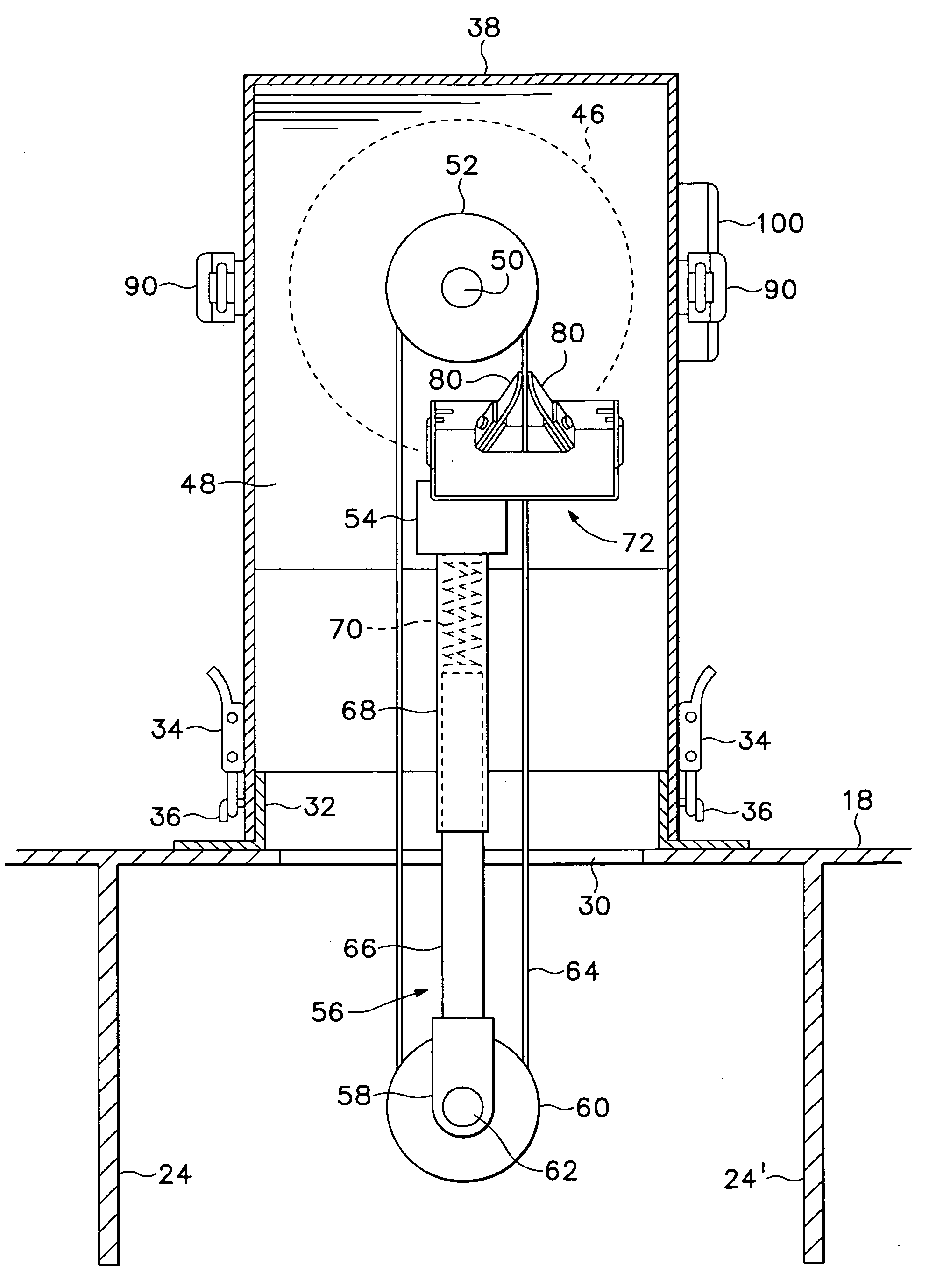
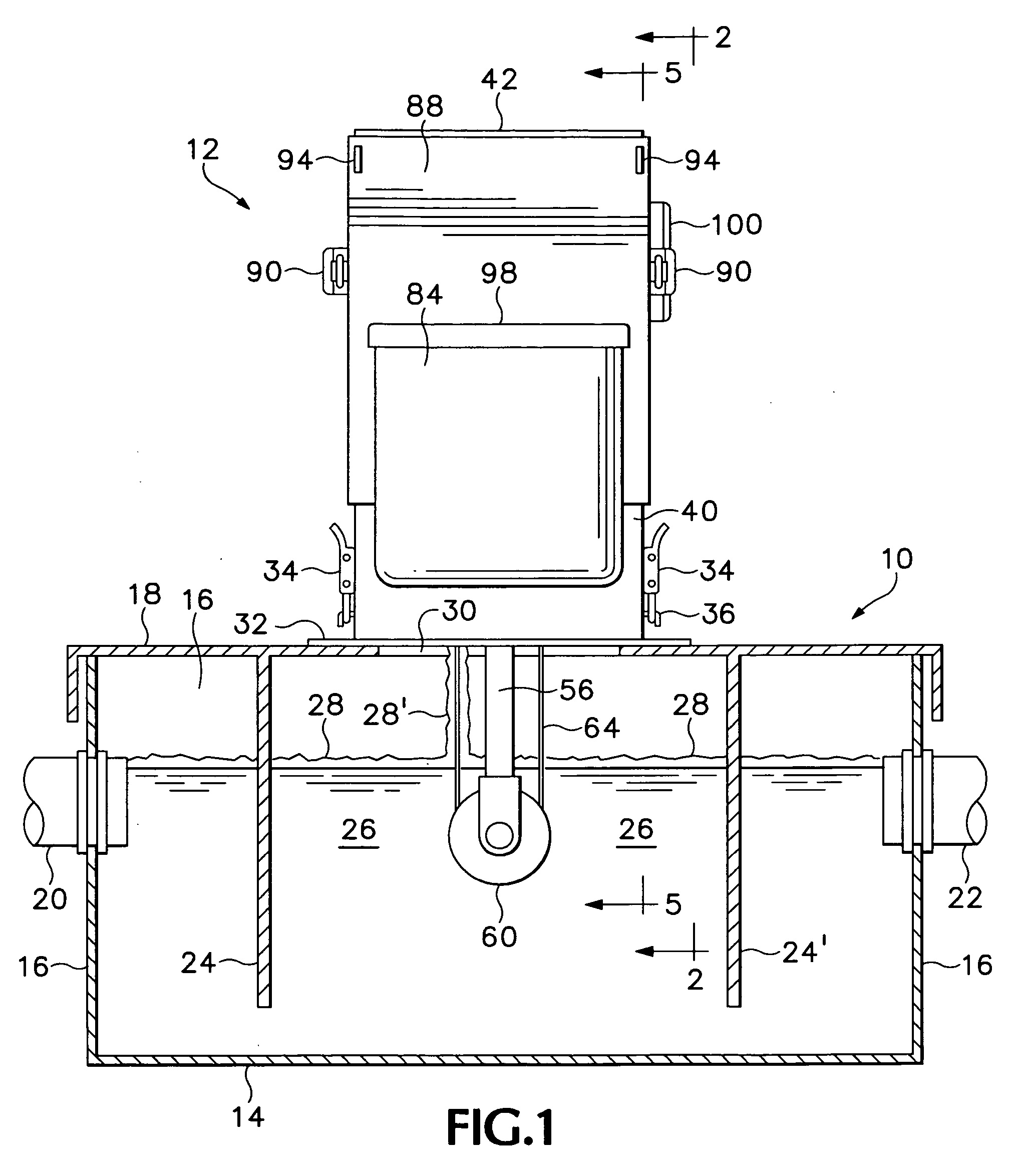
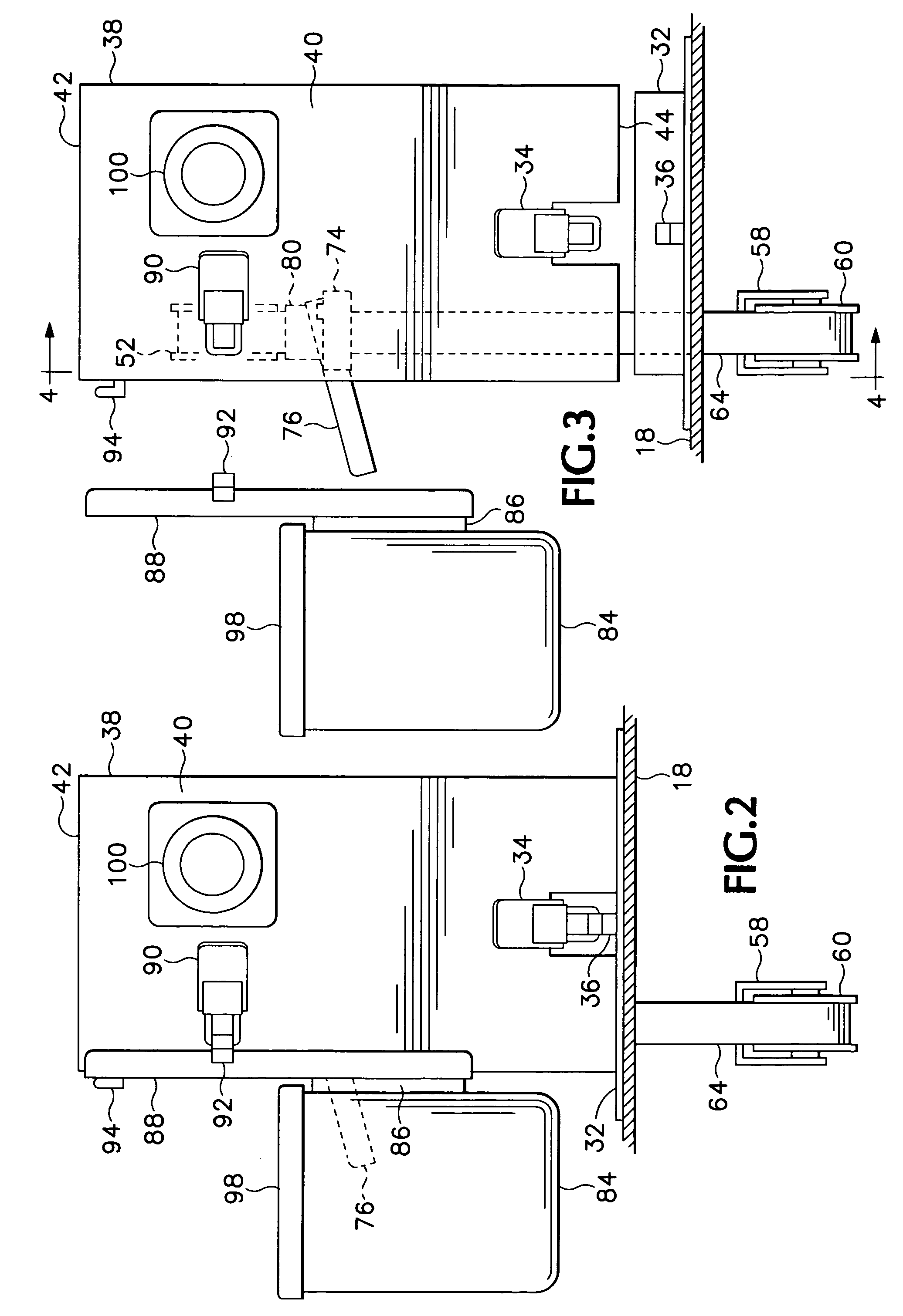
[0024]FIG. 1 illustrates a basic grease trap assembly generally indicated at 10 mounting a tower-type skimmer and grease removal apparatus 12 embodying features of the present invention. For purposes of illustration herein, the embodiment of the invention illustrated in FIGS. 1-7 is shown in a form arranged for retrofit or subsequent installation onto an already-installed, basic grease trap settling tank assembly 10 in order to upgrade the assembly into automatic skimming capability. It is to be understood however that the grease trap settling tank assembly 10 and tower-type grease skimming and removal apparatus may also be provided together as a complete trap apparatus assembly as well. In either case, the basic grease trap tank assembly typically comprises, as shown, a substantially hollow box member or settling tank formed of a bottom wall 14, upstanding side and opposite end walls 16 and a top wall shown herein as a removable top lid member 18 arranged for releasable securement ...


PUM

PropertyMeasurementUnit
Gravityaaaaaaaaaa

Abstract

A grease skimming and removal apparatus for use with grease trap settling tank apparatus provides a vertically elongated, vertically extending tower housing on the top wall of a grease trap tank and provides a power driven, vertically elongated, vertically extending rotating skimmer belt loop arranged to skim and transport grease and oils from wastewater contained in the grease trap tank to a vertically-elevated position above the top wall of the settling tank for gravity discharged therefrom and into a collection vessel releasably secured to the tower housing above the top wall of the grease trap tank.

Description

[0001] This application claims benefit under 35 U.S.C. 119(e) of the priority filing of U.S. Provisional application Ser. No. 60 / 617,812, filed 12 Oct. 2004.BACKGROUND OF THE INVENTION [0002] This invention relates to grease trap assemblies provided in waste water drain line systems, and more particularly to such grease trap assemblies having automatic, powered skimmer arrangements for skimming and removing grease and oils from the wastewater passing through the grease trap assembly prior to exiting through an outlet into the municiple sewer system serving the facility. Such grease trap assemblies are used in connection with commercial food preparation sinks, rinse sinks and dishwashing and utensil washing facilities and such in restaurants, fast food outlets, hospitals, hotels and other large kitchen facilities that produce grease and oil-laden wastewater in order to reduce the amount of grease, cooking oil and other contaminants that are introduced into the municipal sewer system ...

Claims


Application Information

Patent Timeline
IPC IPC(8): B01D17/00
CPCB01D17/0208B01D17/0214B01D17/0202
Inventor WEYMOUTH, BRET M.
Owner WEYMOUTH BRET M
Why Eureka
Try Eureka