
Synchronous delay-line amplification technique

a delay-line amplification and delay-line technology, applied in pulse manipulation, pulse technique, instruments, etc., can solve the problem of significant distortion, the dynamic range of digital-input switching amplifiers is limited by the resolution (or frequency) of the clock signal, and the time resolution of the output pulsewidth cannot be finer than that of the driving clock signal

Active Publication Date: 2006-04-13
JM MGMT GRP LTD LLC
View PDF3 Cites 6 Cited by
  • Summary
  • Abstract
  • Description
  • Claims
  • Application Information

AI Technical Summary

Benefits of technology

[0005] The present invention broadly allows an open-loop switching amplifier to achieve fully synchronous operation. In terms of circuitry, the preferred embodiment includes a ring oscillator based upon a tapped delay line. A counter is clocked from the ring oscillator, periodically comparing incoming more significant data to the value of the counter to form a pulsewidth modulated output waveform...

Problems solved by technology

Resultantly, time resolution of the output pulsewidths cannot be finer than that of the driving clock signal.
Unlike their analog-input equivalents, the dynamic range of digital-input switching amplifiers is therefore limited by the resolution (or frequency) of the clock.
However, significant distortion results from the lack of synchronization between clocked and delay line elements of such an amplifier.

Method used


Image

  • Synchronous delay-line amplification technique
  • Synchronous delay-line amplification technique

Examples


Embodiment Construction

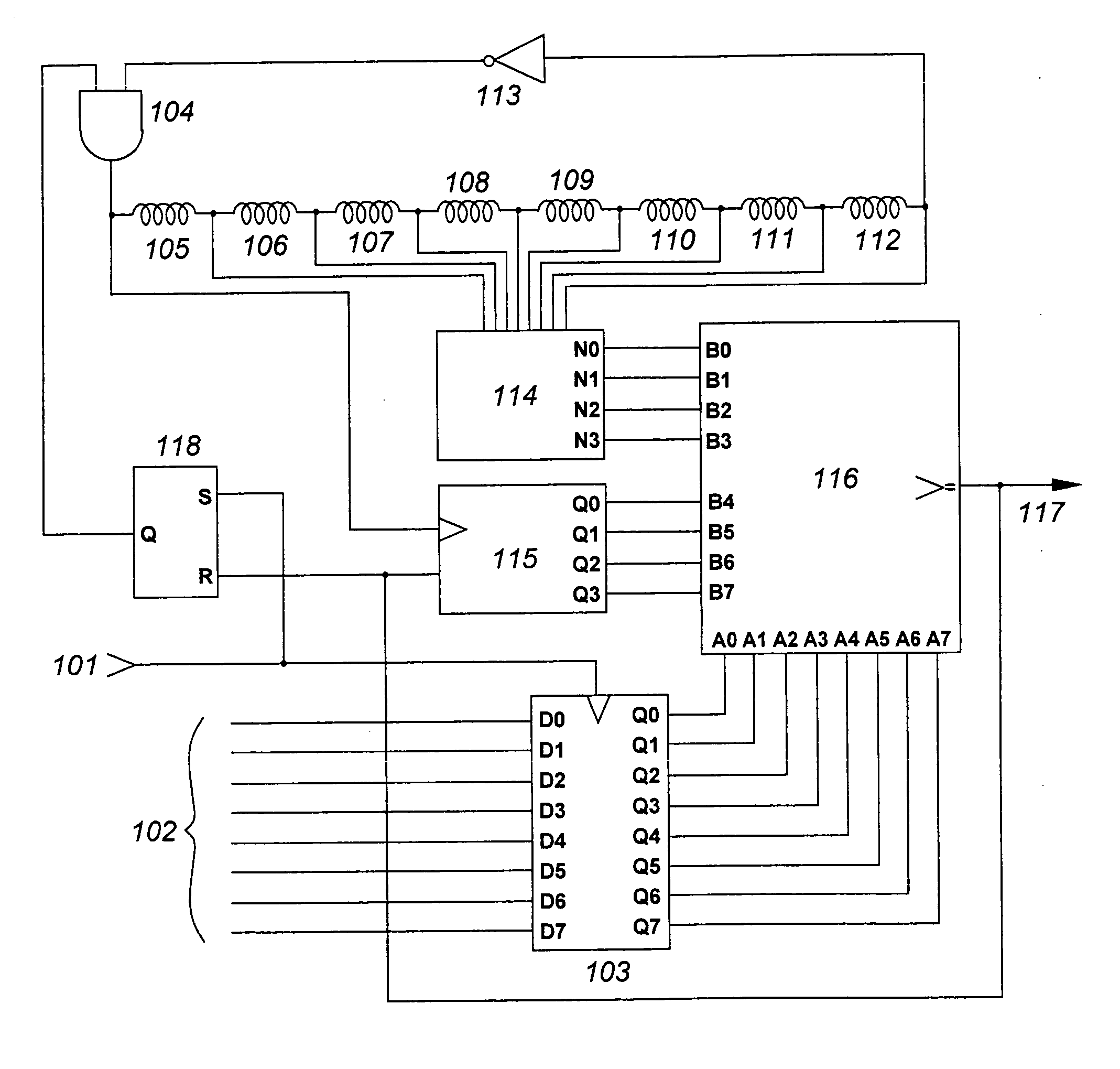
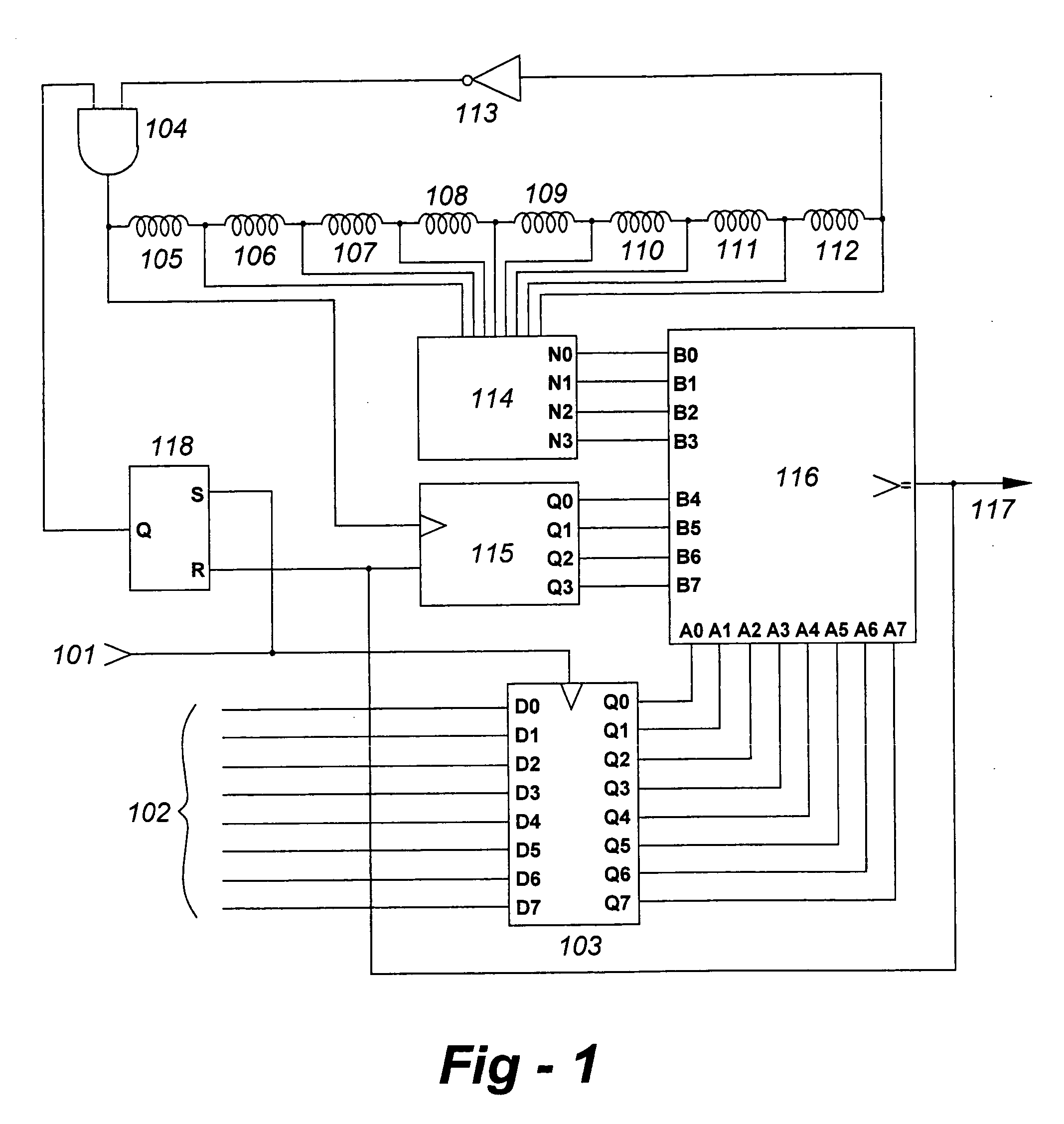
[0007] Referring now to FIG. 1, delay-elements 105, 106, 107, 108, 109, 110, 111, 112 are connected serially, with the ultimate output connected to the input of inverter 113. The output converter 113 is gated by AND gate 104 to then drive delay element 105 as well as the clock input of counter 115. The delay elements 105 through 112 and inverter 113 therefore comprise a ring oscillator which produces a series of bit patterns to decoder 114, and a clock signal to counter 115.

[0008] It can be seen that, in this particular example, eight specific bit patterns will be presented to decoder 114 after each negative-going transition of the clock input of counter 115, and that eight different specific bit patterns will be presented to decoder 114 after each positive-going transition of the clock input of counter 115. Decoder 114 receives the bit patterns from delay elements 105 through 112, and produces a known binary number for each bit pattern at outputs N0, N1, N2, N3. Outputs N0 through...


PUM


Abstract

An open-loop switching amplifier achieves synchronous operation using a ring oscillator based upon a tapped delay line. A counter is clocked from the ring oscillator, periodically comparing incoming more significant data to the value of the counter to form a pulsewidth modulated output waveform. Modulating the effective width of the output waveform in incremental delay line taps is equivalent to incoming less significant data. This technique then effects time-period summation of coarse and fine resolution clocked data.

Description

REFERENCE TO RELATED APPLICATION [0001] This application claims priority from U.S. Provisional Patent Application Ser. No. 60 / 583,507, filed Jun. 28, 2004, the entire content of which is incorporated herein by reference.FIELD OF THE INVENTION [0002] This invention relates generally to switching amplifiers and, in particular, to apparatus and methods enabling an open-loop switching amplifier to achieve synchronous operation. BACKGROUND OF THE INVENTION [0003] Open-loop switching amplifiers with digital inputs typically operate as clock-synchronous devices which deliver two defined voltage levels to a load. Resultantly, time resolution of the output pulsewidths cannot be finer than that of the driving clock signal. Unlike their analog-input equivalents, the dynamic range of digital-input switching amplifiers is therefore limited by the resolution (or frequency) of the clock. While dynamic range may be extended by the use of more than two defined output switching levels, as taught in U...

Claims


Application Information

Patent Timeline
IPC IPC(8): H03K3/03
CPCG06F1/025H03F3/217H03F2200/351H03K3/0315H03K7/08H03K2005/00247
Inventor KIRN, LARRY
Owner JM MGMT GRP LTD LLC
Learn More