
Supplemental parasitic antenna apparatus

a parasitic antenna and antenna technology, applied in the field of radio communication equipment, can solve the problems of significant performance degradation and significant degradation of the antenna performance, and achieve the effect of increasing radiation and/or reception in the frequency range, and increasing radiation and/or reception

Inactive Publication Date: 2006-04-13
SONY ERICSSON MOBILE COMM AB
View PDF12 Cites 9 Cited by
  • Summary
  • Abstract
  • Description
  • Claims
  • Application Information

AI Technical Summary

Benefits of technology

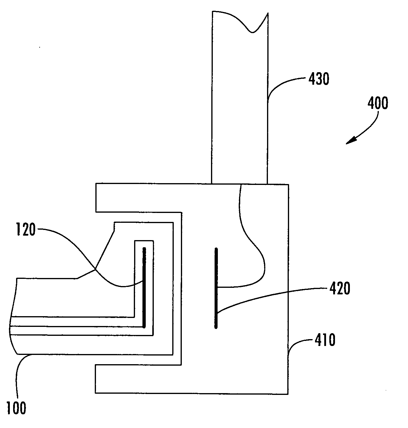
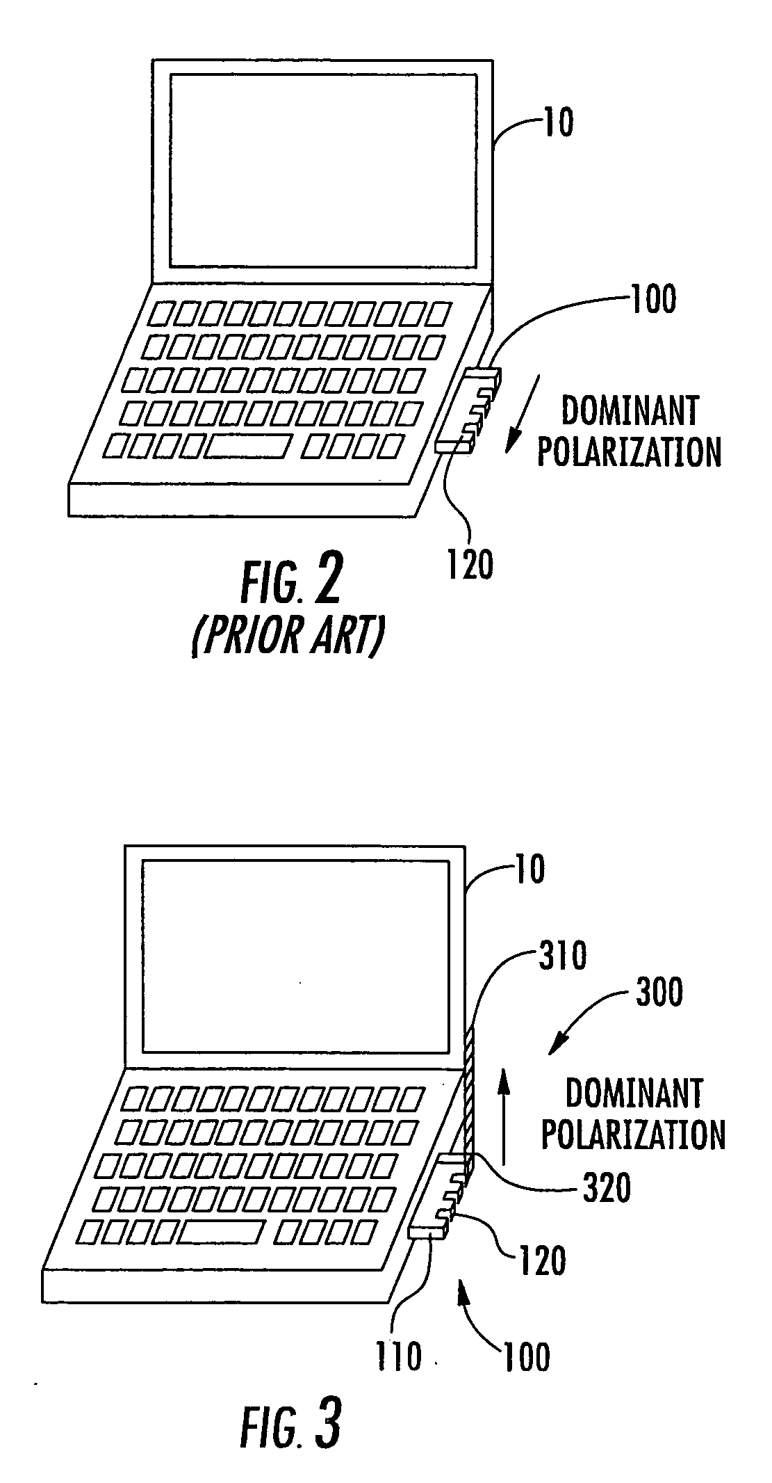
[0005] In some embodiments of the present invention, a supplemental antenna assembly is provided for use with an electronic device having an integral radio antenna, such as a wireless-enabled laptop computer, notebook computer, gaming device, personal digital assistant (PDA), or circuit card, adaptor or other circuit assembly designed be used with such a device. The supplemental antenna assembly includes a parasitic element supported by a frame. The frame is configured to be attached to the housing of the portable device such that an inductive coupling is provided between the parasitic element and the integral radio antenna. The parasitic element may include, for example, an antenna and / or a coupling element, such as a coupling element configured to be connected to an external antenna. In some embodiments, the electronic device may preferentially radiate and / or receive radio signals over a frequency range in the absence of the supplemental antenna assembly, and the supplemental antenna assembly may increase radiation and / or reception in the frequency range. In other embodiments, the supplemental antenna assembly may increase radiation and / or reception at a frequency outside of the frequency range such that, for example, the electronic device supports an alternate second radio application.

Problems solved by technology

Constraints on the size and positioning of such internal antennas may cause antenna performance to be significantly degraded.
The resulting polarization mismatch may lead to significant performance degradation.

Method used


Image

  • Supplemental parasitic antenna apparatus
  • Supplemental parasitic antenna apparatus
  • Supplemental parasitic antenna apparatus

Examples


Embodiment Construction

[0011] Specific exemplary embodiments of the invention now will be described with reference to the accompanying drawings. This invention may, however, be embodied in many different forms and should not be construed as limited to the embodiments set forth herein; rather, these embodiments are provided so that this disclosure will be thorough and complete, and will fully convey the scope of the invention to those skilled in the art. The terminology used in the detailed description of the particular exemplary embodiments illustrated in the accompanying drawings is not intended to be limiting of the invention. In the drawings, like numbers refer to like elements.

[0012] As used herein, the singular forms “a”, “an” and “the” are intended to include the plural forms as well, unless expressly stated otherwise. It will be further understood that the terms “includes,”“comprises,”“including” and / or “comprising,” when used in this specification, specify the presence of stated features, integer...


PUM


Abstract

A supplemental antenna assembly is provided for use with an electronic device having an integral radio antenna, such as a wireless-enabled laptop computer, notebook computer, gaming device, personal digital assistant (PDA), or circuit card (e.g., a PCMCIA card) or other circuit assembly designed be used with such a device. The supplemental antenna assembly includes a parasitic element supported by a frame. The frame is configured to be attached to the housing of the portable device such that an inductive coupling is provided between the parasitic element and the integral radio antenna. The parasitic element may include, for example, an antenna and / or a coupling element, e.g., a coupling element configured to be connected to an external antenna.

Description

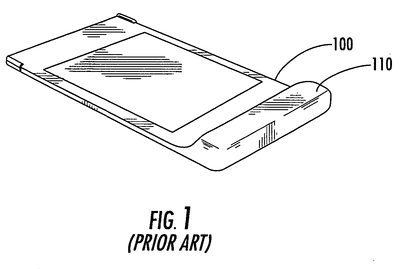
BACKGROUND OF THE INVENTION [0001] The present invention relates to radio communications apparatus, and more particularly, to radio antenna apparatus. [0002] Computing devices, such as laptop computers, notebook computers, pocket PCs, personal digital assistants (PDAs), gaming devices, and the like, now commonly possess wireless communications capabilities. For example, many laptop and notebook computers now incorporate radio communications circuitry configured to communicate with, for example, WiFi networks and / or public cellular networks. Such circuitry may be integrated in the computer and / or may be provided in a circuit assembly, such as a PC card or a USB adapter, which is plugged into the computer. Similar cards and / or adapters may be used with other electronic devices, such as PDAs and computer peripherals (e.g., printers, scanners, and the like) [0003] Such wireless communications circuitry may be configured to connect to an external radio antenna and / or may include an integ...

Claims


Application Information

Patent Timeline
Patent Type & Authority Applications(United States)
IPC IPC(8): H01Q1/24
CPCH01Q1/22H01Q1/2275
Inventor HAYES, GERARD JAMES
Owner SONY ERICSSON MOBILE COMM AB
Learn More