

Heating line pattern structure of defogger
- Summary
- Abstract
- Description
- Claims
- Application Information
AI Technical Summary
Benefits of technology
Problems solved by technology
Method used
Image

Examples
embodiment 1
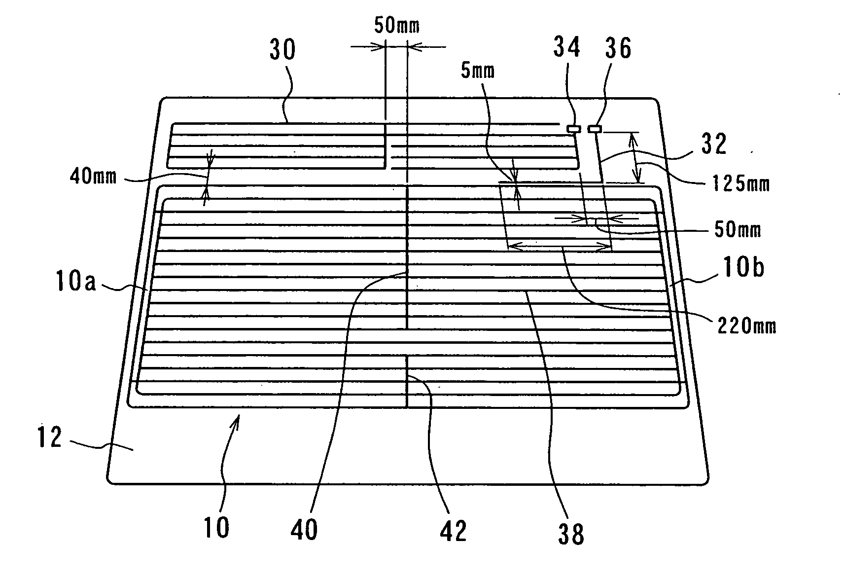
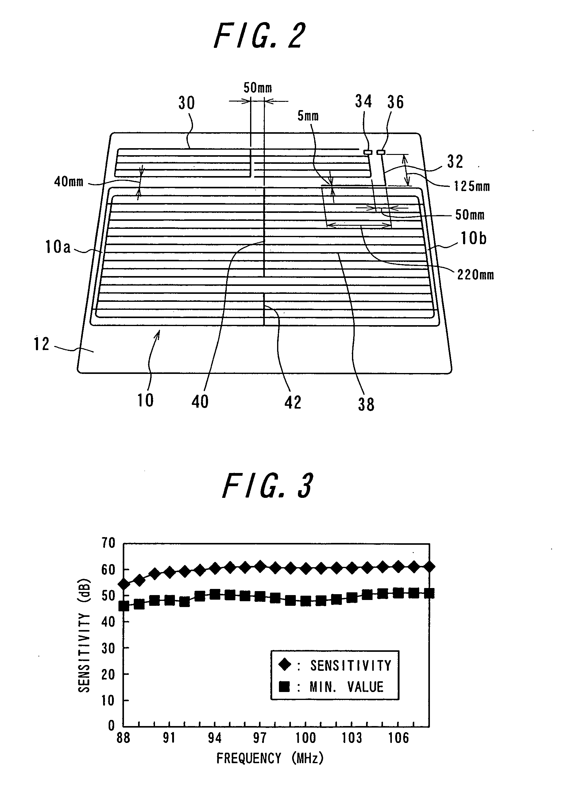
[0040] A defogger 10, AM antenna 30, FM antenna 32 are formed on a rear window glass panel 12 of a motor vehicle as shown in FIG. 2.
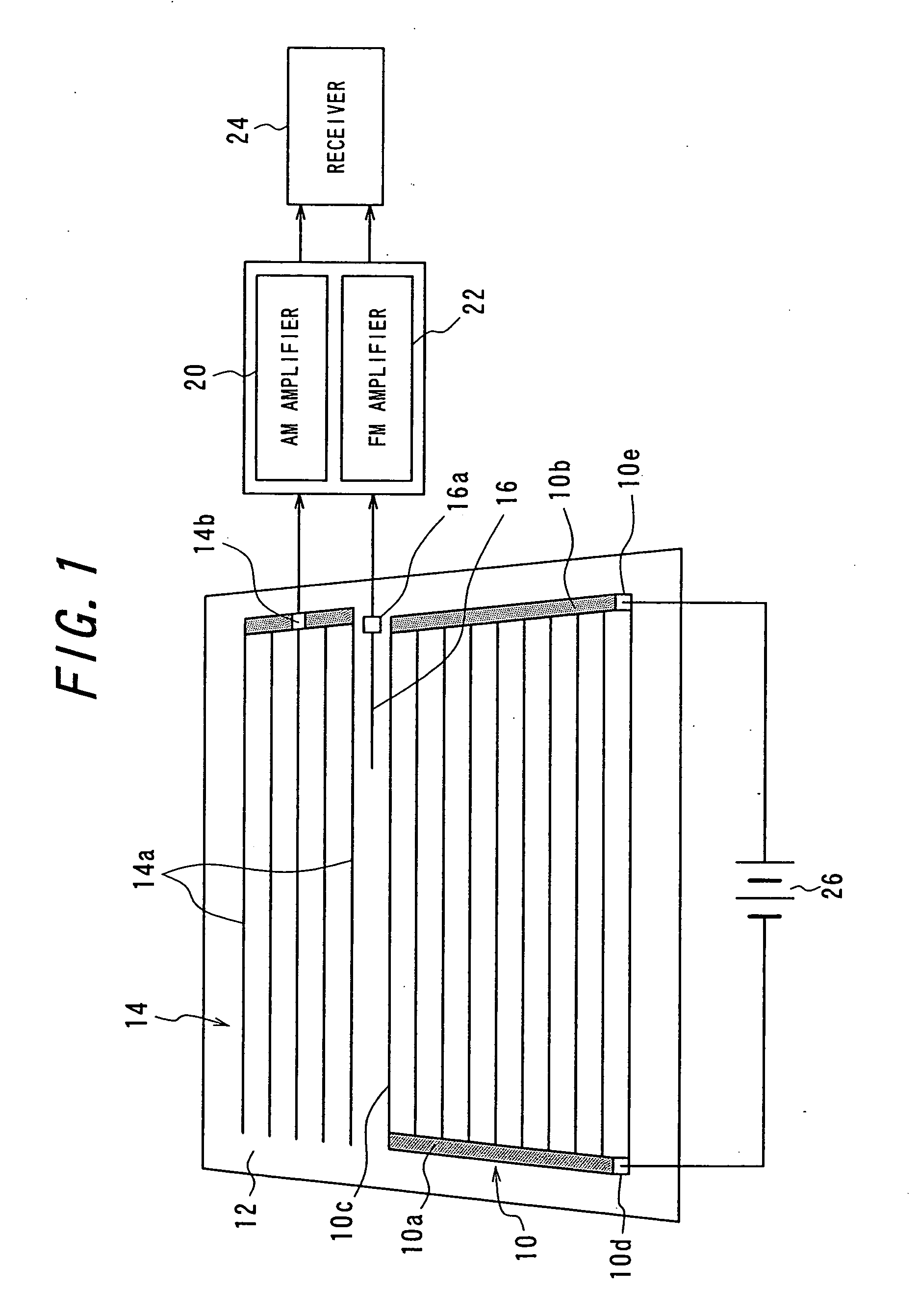
[0041] Different from the AM antenna 14 in FIG. 1, the AM antenna 30 has an antenna pattern such that a plurality of horizontal linear conductors (five conductors in this embodiment) are arranged at 25 mm pitch in two regions partitioned by three vertical linear conductors, respectively, and the ends of four horizontal linear conductors in the right region are opened without being connected to the vertical linear conductor as shown in the figure. An FM antenna 32 is structured by one bent conductor different from the FM antenna 16 structured by a linear conductor in FIG. 1. In the figure, reference numeral 34 designates an AM feeding terminal and 36 an FM feeding terminal.
[0042] A heating line pattern of a defogger is formed by a plurality of heating lines 38 (18 lines in the present embodiment) arranged in parallel at 30 mm pitch between bus-bars 10a...
embodiment 2
[0049] A heating line pattern of the defogger according to the present embodiment is shown in FIG. 5. The heating line pattern according to the present embodiment is the same as that shown in FIG. 2 other than the length of the vertical linear conductor. That is, the vertical linear conductor 44 is longer than the vertical linear conductor 40 in FIG. 2, and the vertical linear conductor 46 is shorter than the vertical linear conductor 42 in FIG. 2. The conductor 44 extends across 12 heating line intervals and the conductor 46 extends across 3 heating line intervals. It is the same as in FIG. 2 that the conductor 44 and conductor 46 are separated across 2 intervals.
[0050] The measured sensitivities of the antenna in FIG. 5 are shown in Table 2. FIG. 6 shows the graph illustrating the minimum values of the measured sensitivities. FIG. 7 shows the measured directivities in the range of 88-108 MHz. Upward direction in the figure designates the forward direction of a motor vehicle.
TAB...
embodiment 3
[0052] A heating line pattern of the defogger according to the present embodiment is shown in FIG. 8. The heating line pattern of this embodiment is that where a T-shaped conductor 48 is added in a space under the defogger 40 in FIG. 5. The T-shaped conductor 48 is upside down in the figure and is composed of a vertical linear conductor 50 of 150 mm and a horizontal linear conductor 52 of 400 mm, the top end of the conductor 50 being connected the bottommost heating line 38.
[0053] The measured sensitivities of the antenna in FIG. 8 are shown in Table 3. FIG. 9 shows the graph illustrating the minimum values of sensitivities. FIG. 10 shows the measured directivities in the range of 88-108 MHz. Upward direction in the figure designates the forward direction of a motor vehicle.
TABLE 3Sensitivity (dB)f (MHz)max.ave.min.max. − min.8868.461.650.318.18968.661.849.718.99068.762.049.119.69168.261.748.619.69267.761.347.220.59367.761.249.218.59467.761.049.718.09567.460.649.218.29667.160.249...
PUM
 Abstract
Description
Claims
Application Information