
Slider, manufacturing method thereof, and head suspension assembly with the same

Inactive Publication Date: 2006-04-13
SAE MAGNETICS (HK) LTD
View PDF14 Cites 14 Cited by
  • Summary
  • Abstract
  • Description
  • Claims
  • Application Information

AI Technical Summary

Benefits of technology

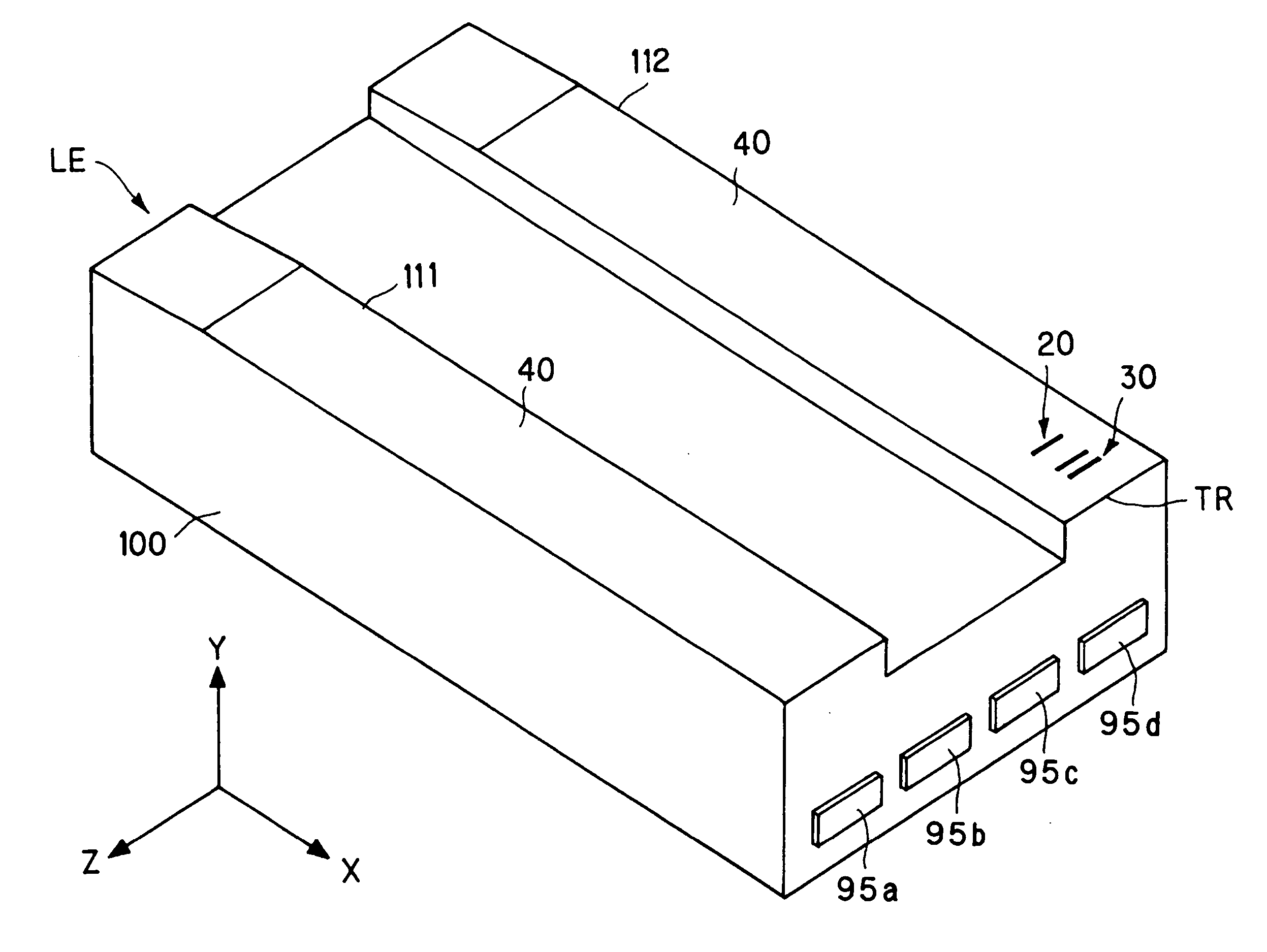
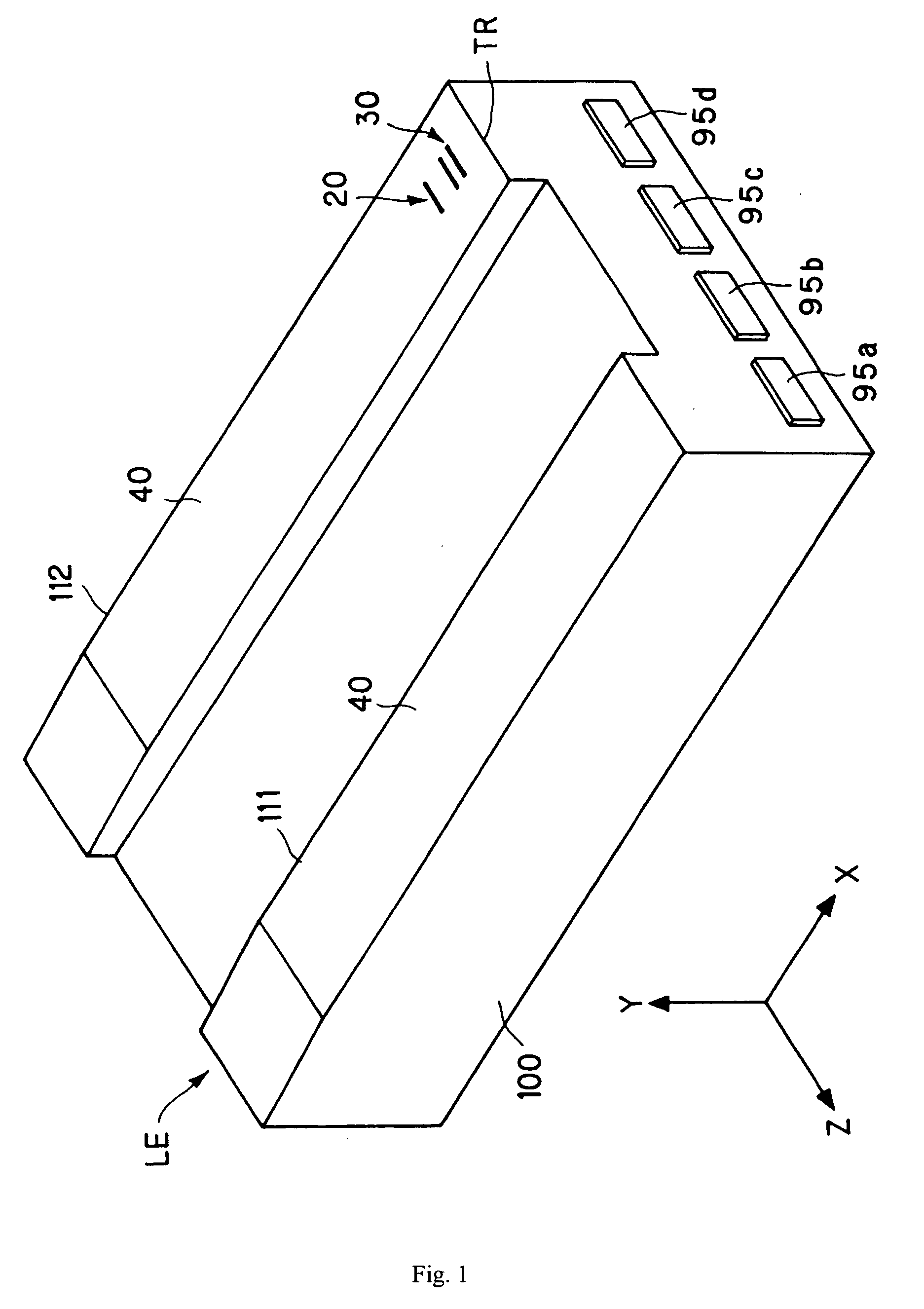
[0023] The slider provided by the invention includes a substrate, a head element formed on the substrate and a protecting film formed on at least one portion of one surface of the substrate, wherein said surface faces the magnetic recording medium. Viewed from one surface of the substrate, said protecting film comprises in turn a first DLC (diamond like carbon) film and a second DLC film, wherein the carbon film density of said first DLC film is less than 3.1 (g / cm3), whereas the carbon film density of said second DLC film is more than 3.1 (g / cm3). By such structure, the slider of the invention takes advantages of very excellent long term wearability and corrosive-resistance which are not presented in conventional technology.

Problems solved by technology

As it is difficult to attach the DLC film onto a metallic film of Fe or Fe alloy, accordingly, it is very difficult to directly form and tightly bond the DLC film on the metal.
However, in Japanese patent application publication No. 2002-8217, because the two carbon films with completely different characteristic are used concurrently, a long term protection (including protection from vibration) will not be achieved even if a short term protection can be gotten.
Moreover, the protective thin film has a complex structure and it is difficult to control manufacturing process for forming the desirable protective thin film so as to make the thin film not reliable.

Method used


Image

  • Slider, manufacturing method thereof, and head suspension assembly with the same
  • Slider, manufacturing method thereof, and head suspension assembly with the same
  • Slider, manufacturing method thereof, and head suspension assembly with the same

Examples


embodiment 1

[0083] Performing the step S1-S3 shown in FIG. 5 step by step and cutting the wafer with compound read / write elements incorporated therein into a plurality of slices with a predetermined size, and forming a plurality of sample row bars (similar to the row bars 116 shown in FIG. 6b, i.e. a plurality of bars with a same structure) by such as a diamond cutter.

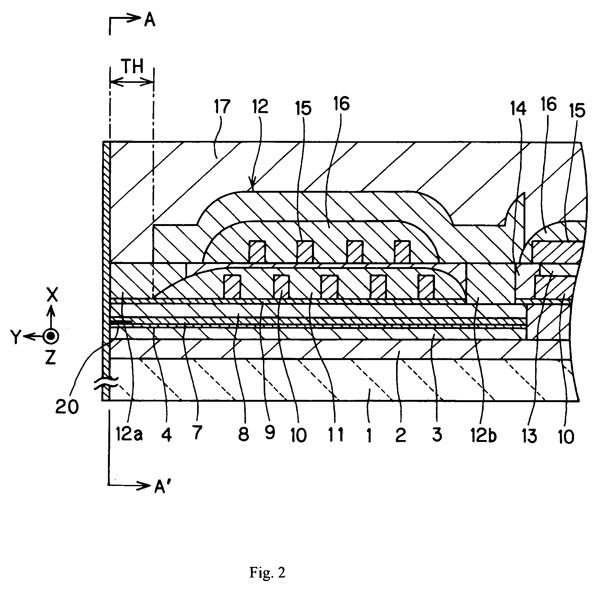
[0084] The sample row bar has a multi-filmed configuration as shown in FIGS. 2-4, which comprises an AlTiC base plate acting as the wafer of the substrate 1, an aluminum layer with a thickness of 5 μm functioning as the undercoat 2, a permalloy layer with a thickness of 2 μm serving as the bottom magnetic-shielding layer 3, a Ta layer with a thickness of 0.05 μm used as the first covering layer 4, a GMR element 20 (a more detailed illustration will be given later), a Ta layer with a thickness of 0.05 μm used as the second covering layer 7, a permalloy layer with a thickness of 4 μm as the top magnetic-shielding layer 8, and a NiF...


PUM


Abstract

A slider of the invention includes a substrate, a head element formed on the substrate and a protecting film formed on at least one portion of one surface of the substrate facing a magnetic recording medium. The protecting film comprises a base film, first DLC (diamond like carbon) film adjacent the substrate and a second DLC film. The carbon film density of said first DLC film is less than 3.1 (g / cm3) and the carbon film density of said second DLC film is more than 3.1 (g / cm3).

Description

FIELD OF THE INVENTION [0001] The present invention relates to a slider incorporating a thin protecting film which is wearable and corrosive-resistant, and manufacturing method of the slider, and a head suspension assembly (HSA) incorporating the slider. BACKGROUND OF THE INVENTION [0002] Disk drives have been widely used as external storage devices of small computer systems. [0003] Presently, disk drives are developed to have a high storage density while having a low profile and big storage capacity. So, it is provided that a slider comprising a substrate and a head element formed on the substrate by thin-film technology. In these sliders, many reading head elements, such as AMR (anisotropy magneto-resistive) element, GMR (giant magneto-resistive) element and TMR (tunnel magneto-resistive) have been developed for satisfying a requirement of high recording density. In addition, a CPP (current perpendicular to plane) type GMR element can also be used as a reading head element in the ...

Claims


Application Information

Patent Timeline
IPC IPC(8): G11B5/60
CPCG11B5/102G11B5/187G11B5/40G11B5/6005G11B5/3173G11B5/6082
Inventor UEDA, KUNIHIRO
Owner SAE MAGNETICS (HK) LTD
Learn More