Methods and systems for rate control in image compression

a rate control and image compression technology, applied in the field of image compression, can solve the problems of reducing the compression ratio, reducing the quality of the reconstructed image, and reducing so as to reduce the amount of compressed data, reduce image fidelity, and achieve efficient rate control

Active Publication Date: 2006-04-13
NVIDIA CORP
View PDF23 Cites 11 Cited by
  • Summary
  • Abstract
  • Description
  • Claims
  • Application Information

AI Technical Summary

Benefits of technology

[0012] Accordingly, a system and / or method that can efficiently compress image data to a target compression ratio would be advantageous. Embodiments in accordance with the present invention provide this and other advantages.
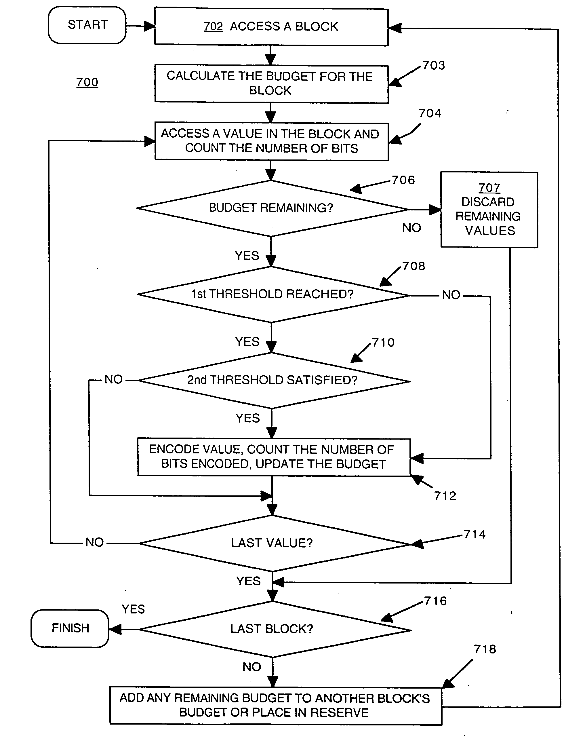
[0017] In summary, according to embodiments of the present invention, rate control is efficiently achieved by establishing a budget that is distributed amongst the blocks of image data and enforced on a block-by-block basis. In one embodiment, the transformed and quantized values in a block that are run-length encoded later, and that generally correspond to the values that contribute less to image fidelity, are discarded (not encoded), reducing the amount of compressed data without significantly reducing image fidelity. In another embodiment, the “smaller” transformed and quantized values (e.g., those values that do not satisfy the second threshold mentioned above), which generally do not contribute significantly to image fidelity, are discarded (not encoded), also reducing the amount of compressed data without significantly reducing image fidelity.

Problems solved by technology

Conversely, smaller quantization steps mean that the uncompressed data is more closely represented, thereby increasing the quality of the reconstructed image but reducing the compression ratio.
Otherwise, if too little file space is allocated, then the compressed data will not fit into the allocated file space or may exceed the available transfer bandwidth.
Unfortunately, for an input amount of data (uncompressed) and a selected set of quantization values, it is not possible to accurately predict the amount of output data (compressed).
This uncertainty in the size of the output bitstream is problematic because, as mentioned above, the amount of compressed data may be too large to properly fit into the allocated file space or may be too large to transfer given an allocated transfer bandwidth.
Thus, conventional techniques can require multiple iterations, increasing both encoding time and the use of computing resources (power, memory, processor cycles, etc.).
The risk of exceeding the target bitstream or file size can be reduced by choosing larger quantization values, but this comes at the expense of reducing too heavily the quality of the reconstructed image.

Method used


Image

  • Methods and systems for rate control in image compression
  • Methods and systems for rate control in image compression
  • Methods and systems for rate control in image compression

Examples


Embodiment Construction

[0031] Reference will now be made in detail to the various embodiments of the present invention, examples of which are illustrated in the accompanying drawings. While the invention will be described in conjunction with these embodiments, it will be understood that they are not intended to limit the invention to these embodiments. On the contrary, the invention is intended to cover alternatives, modifications and equivalents, which may be included within the spirit and scope of the invention as defined by the appended claims. Furthermore, in the following detailed description of the present invention, numerous specific details are set forth in order to provide a thorough understanding of the present invention. However, it will be understood that the present invention may be practiced without these specific details. In other instances, well-known methods, procedures, components, and circuits have not been described in detail so as not to unnecessarily obscure aspects of the present in...


PUM


Abstract

Methods and systems for compressing an image are described. A plurality of transformed and quantized values associated with a block of image data is accessed. The block corresponds to a position within the image. A count of the number of bits encoded during run-length encoding of the block is made. Run-length encoding of the block is concluded should the count reach a limit.

Description

FIELD OF THE INVENTION [0001] Embodiments of the present invention generally relate to image compression. BACKGROUND ART [0002] Image data can be compressed (encoded) to reduce the amount of data associated with an image without significantly affecting the fidelity of the image. Image compression standards, such as the JPEG (Joint Photographic Experts Group) compression standard, work well to reduce the amount of image data. [0003] In JPEG encoding, the input image is decomposed into MCUs (macro code units or minimum coded units), also referred to as macroblocks. Each MCU includes a number of blocks, typically an array of 8×8 values. A block can be associated with each of the separate image or color components of the image. For example, an MCU may include a luminance block (e.g., a Y-block) and two chrominance blocks (e.g., a U-block and a V-block). [0004] A discrete cosine transform (DCT) is performed to convert each block into frequency space (referred to as DCT coefficients). Typ...

Claims


Application Information

Patent Timeline
Patent Type & Authority Applications(United States)
IPC IPC(8): G06K9/36
CPCH04N19/176H04N19/115H04N19/132H04N19/152H04N19/93H04N1/41G06V10/20G06V10/40
Inventor TJANDRASUWITA, IGNATIUSZHONG, LEFAN
Owner NVIDIA CORP
Why Eureka
Try Eureka