Communication terminal device and radio communication method

a communication terminal and radio communication technology, applied in power management, digital transmission, wireless communication, etc., can solve the problems of packet transmission only ever being performed at a low transmission rate in order, the reception quality degrades in other communication terminals, and the unexpected increase in reception power, so as to increase the power consumption of the communication terminal. , the effect of decreasing the system capacity

Inactive Publication Date: 2006-04-13
PANASONIC CORP
View PDF7 Cites 64 Cited by
  • Summary
  • Abstract
  • Description
  • Claims
  • Application Information

AI Technical Summary

Benefits of technology

[0014] It is an object of the present invention to provide a communication terminal apparatus and radio communication method capable of reporting a packet transmission method without transmitting a dedicated signal to a base station apparatus, decreasing system capacity, or increasing communication terminal apparatus power consumption.

Problems solved by technology

On the other hand, however, a drawback of the first packet transmission method is that, when a communication terminal apparatus performs soft handover (SHO) at the edge of a cell, an unexpected increase in reception power occurs in a base station apparatus that has not performed scheduling for that communication terminal apparatus, and reception quality degrades in other communication terminals.
On the other hand, however, a drawback of the second packet transmission method is that packet transmission can only ever be performed at a low transmission rate in order to suppress interference with other cells.
However, having a communication terminal apparatus generate and transmit a new signal for reporting the packet transmission method leads to problems of increased uplink interference, decreased system capacity, and higher communication terminal apparatus power consumption.

Method used


Image

  • Communication terminal device and radio communication method
  • Communication terminal device and radio communication method
  • Communication terminal device and radio communication method

Examples


embodiment 1

[0024] In Embodiment 1, a mode is described in which, when a communication terminal apparatus transmits packet data using predetermined transmission parameters independently of base station apparatus scheduling (the second packet transmission method), information requesting scheduling (hereinafter referred to as “SRQ information”) is not transmitted to the base station apparatus. SRQ information is information indicating the amount of data, transmission rate, or usable transmission power requested by a communication terminal apparatus.

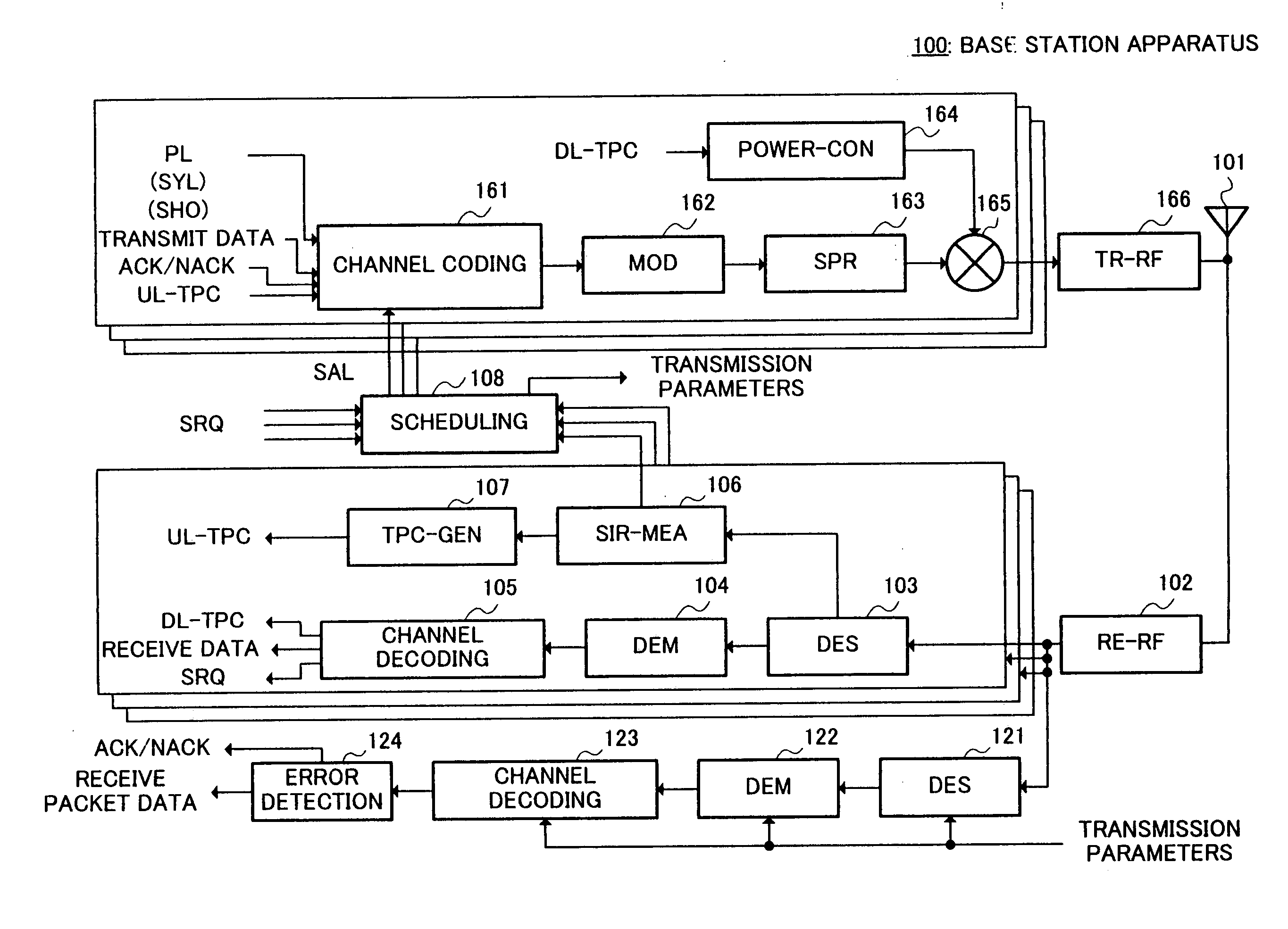
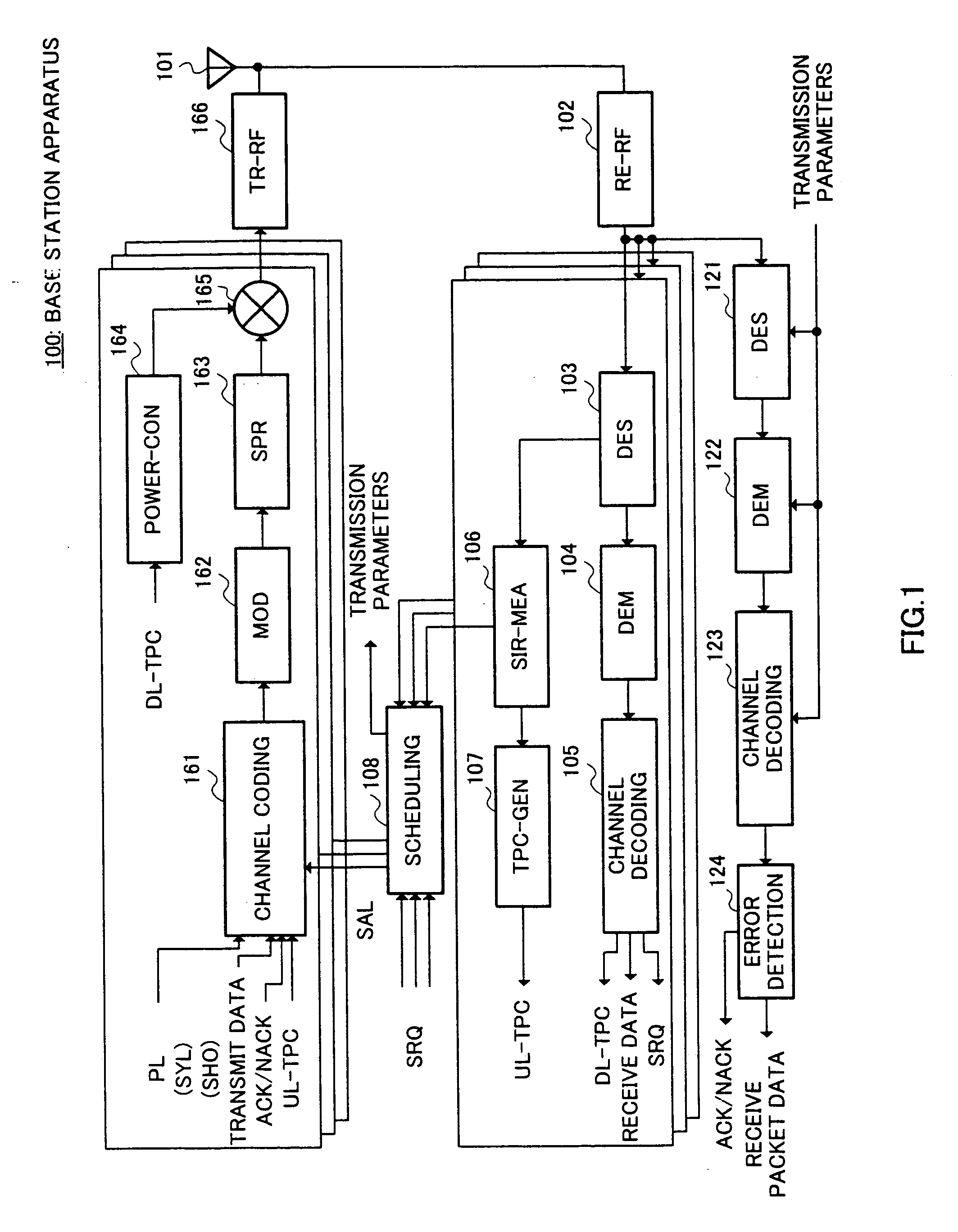
[0025] First, the operation of each component part of a base station apparatus 100 according to this embodiment will be described using the block diagram in FIG. 1.

[0026] A receiving radio section (RE-RF) 102 converts a radio frequency received signal received by an antenna 101 to a baseband digital signal, and outputs this signal to a despreading section (DES) 103 and despreading section (DES) 121.

[0027] A number of despreading sections 103 are pro...

embodiment 2

[0075] In Embodiment 2, a mode is described in which, when a communication terminal apparatus transmits packet data using predetermined transmission parameters independently of base station apparatus scheduling (the second packet transmission method), SRQ information of a specific value for which packet data transmission is never permitted is transmitted.

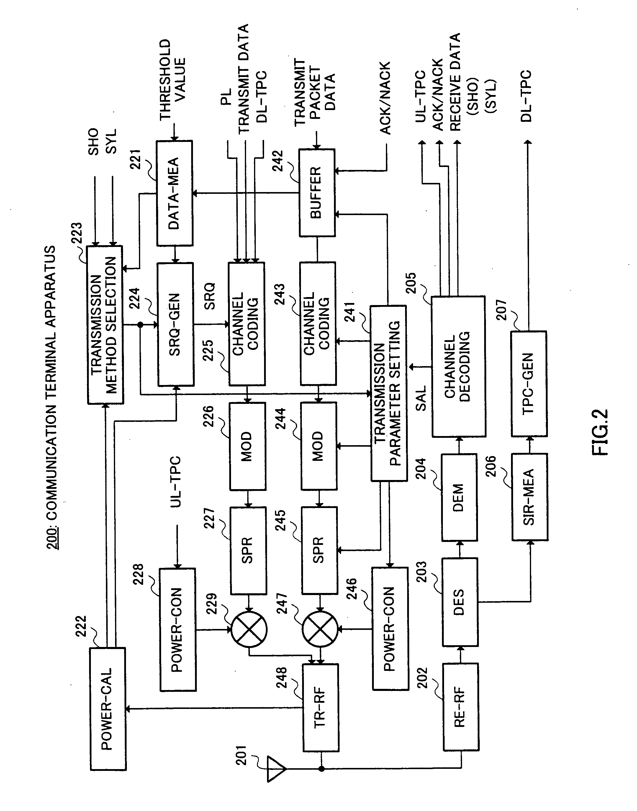
[0076] In Embodiment 2, the configurations of abase station apparatus and a communication terminal apparatus are the same as those of Embodiment 1 shown in FIG. 1 and FIG. 2, and only the internal configuration of scheduling section 108 of a base station apparatus and the operation of SRQ information generation section 224 of a communication terminal apparatus differ.

[0077] SRQ information generation section 224 of this embodiment holds a table indicating the relationship between the amount of data in buffer 242, usable transmission power, and SRQ information, as shown in FIG. 6. Usable transmission power is expressed in decibels ...


PUM


Abstract

A transmission method selection section (223) selects either a first packet transmission method or a second packet transmission method. When the first packet transmission method is selected, an SRQ information generation section (224) generates SRQ (scheduling request) information based on the amount of data calculated by a data amount measuring section (221) and/or the retention time thereof, and the transmission power that can be used for packet data transmission calculated by a transmission power calculation section (222). On the other hand, when the second packet transmission method is selected, the SRQ information generation section (224) does not perform SRQ information generation, or generates SRQ information of a specific value for which packet data transmission is never permitted. By this means, in a radio communication system in which packet transmission is performed on uplinks and the packet transmission method is switched adaptively, the packet transmission method can be reported without transmitting a dedicated signal to a base station apparatus.

Description

TECHNICAL FIELD [0001] The present invention relates to a communication terminal apparatus and radio communication method used in a radio communication system in which packet transmission is performed in uplinks. BACKGROUND ART [0002] A packet transmission method called HSDPA (High-Speed Downlink Packet Access) is known as a technology for transmitting packet data in a downlink (see patent document 1, for example). [0003] With HSDPA, one physical channel is shared by a plurality of communication terminal apparatuses by means of time division. Therefore, a base station apparatus determines a destination communication terminal apparatus to which packet data is to be transmitted and packet data transmission parameters in predetermined time units (generally called “scheduling”). Scheduling is performed based on the amount of data the base station apparatus transmits to a communication terminal apparatus, permissible delay time, communication quality, and so forth, for example. [0004] On...

Claims


Application Information

Patent Timeline
Patent Type & Authority Applications(United States)
IPC IPC(8): H04B7/00H04B7/005H04L1/00H04L1/18H04W52/28H04W52/34H04W72/12H04W76/02
CPCH04L1/0001H04L1/1887H04W36/18H04W52/286H04W52/346H04W72/1284H04W72/21
Inventor IOCHI, HITOSHISUZUKI, HIDETOSHISEIDEL, EIKO
Owner PANASONIC CORP
Why Eureka
Try Eureka