N-phase n+1 bridge arm inverter and modulation method thereof

a technology of inverter and bridge arm, which is applied in the direction of control system, electrical apparatus, ac motor control, etc., can solve the problems of limiting the operating increasing the cost of the entire driving system, and narrow speed range of the motor, so as to reduce the cost of the device, reduce the current stress of the power device of the bridge arm, and improve the operating efficiency of the system

Active Publication Date: 2021-02-11
HUAZHONG UNIV OF SCI & TECH
View PDF0 Cites 0 Cited by
  • Summary
  • Abstract
  • Description
  • Claims
  • Application Information

AI Technical Summary

Benefits of technology

[0021](4) In the N-phase N+1 bridge arm inverter, except for bridge arm 1 and bridge arm N+1, the other bridge arms do not circulate zero-axis current. Therefore, in the N+1 bridge arm N-phase inverter, the current stress of the bridge arm power device is low, which further reduces the cost of the device and the operating efficiency of system is high.

Problems solved by technology

(2) In this topology, the maximum fundamental wave voltage amplitude that can be generated in the output voltage is about half of the DC bus voltage, which leads to a narrow speed range of the motor and limits the operating range of the motor.
To improve the operating range of the motor, there is necessity to increase the DC bus voltage, which will increase cost of the entire driving system, while reducing the reliability and power density.
When a stator winding of a certain phase in the motor fails, voltage of stator windings of other phases which are properly functioning will be affected, and consequently leads to failure of the motor and resulted in worse fault tolerance.
Therefore, in the field of driving multi-phase motor, it has been difficult to reconcile the contradictions between performance, cost, and power density of motor driver and it is hard to reach an optimal matching solution between them.

Method used


Image

  • N-phase n+1 bridge arm inverter and modulation method thereof
  • N-phase n+1 bridge arm inverter and modulation method thereof
  • N-phase n+1 bridge arm inverter and modulation method thereof

Examples


Embodiment Construction

[0027]In order to make the purposes, technical solutions and advantages of the disclosure clearer, the disclosure will be further described in detail below with reference to the accompanying drawings and embodiments. It should be understood that the specific embodiments described herein are only used to explain the disclosure and are not intended to limit the disclosure.

[0028]In view of the defects of related art, the disclosure can reduce the number of power devices in the inverter topology, reduce the capacity of the inverter system, reduce the cost of drive system, increase power density, improve DC voltage utilization rate, enhance the topology fault tolerance, and realize control of complete freedom of stator current.

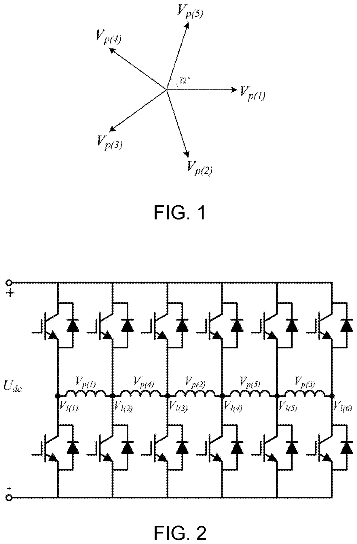
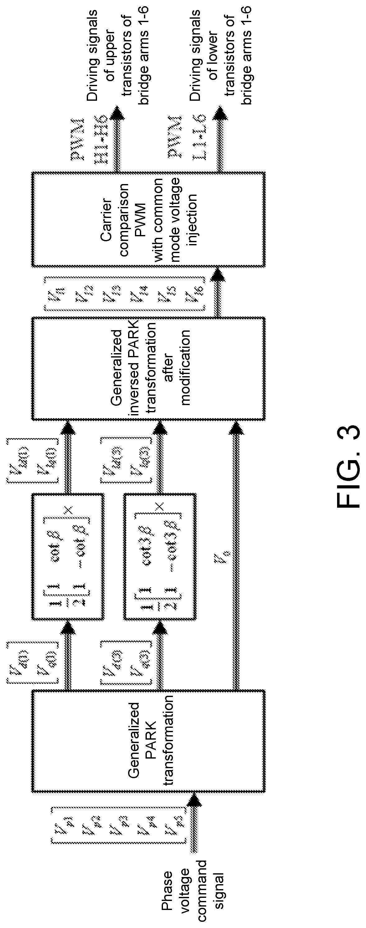
[0029]To achieve the above purpose, in a first aspect, the disclosure provides an N-phase N+1 bridge arm inverter topology, including: bridge arm 1 to bridge arm n+1, a total of N+1 bridge arms, wherein N(=n) is the total phase number of the motor, N is an odd numb...


PUM


Abstract

The disclosure provides an N-phase N+1 bridge arm inverter, including: N+1 bridge arms, wherein each of the bridge arms includes an upper bridge arm power switching device and a lower bridge arm power switching device, upper node of the upper bridge arm power switching device in each of the bridge arms is connected to a DC bus voltage, lower node of the lower bridge arm power switching device is connected to a power ground, and lower node of the upper bridge arm power switching device is connected to upper node of the lower bridge arm power switching device as an output node of the bridge arm. N is a total phase number of a motor, N is an odd number, and N is greater than 3.

Description

BACKGROUNDTechnical Field[0001]The disclosure belongs to the field of AC motor and drive control, and more specifically, relates to an N-phase N+1 bridge arm inverter topology structure and a modulation method thereof.Description of Related Art[0002]In recent years, due to the advantages of multi-phase motors such as small torque ripple, low requirement in capacity of power device, and strong capability for fault tolerance, multi-phase motors and the control technologies thereof have attracted increased attention. In the study of driving multi-phase motor, the half-bridge inverter topology is the basic topology structure of conventional multi-phase inverters.[0003]In the half-bridge inverter structure, one end of the motor stator winding of the multi-phase motor is connected to the phase bridge arm, and another end is in a star connection (or a Y connection) to form a neutral point. The topology structure has the following defects.[0004](1) Since the stator winding of the motor has ...

Claims


Application Information

Patent Timeline
Patent Type & Authority Applications(United States)
IPC IPC(8): H02P27/12
CPCH02P27/12H02P21/28H02P27/08H02P25/22H02P21/26
Inventor JIANG, DONGLI, ANLIU, ZICHENG
Owner HUAZHONG UNIV OF SCI & TECH
Why Eureka
Try Eureka