
Animal-use artificial inseminator

a technology of artificial insemination and animal use, which is applied in the field of improved animal-use artificial insemination, can solve the problems of requiring specialized personnel for operation, affecting the success rate of insemination, and requiring additional manpower, so as to prevent the occurrence of semen backflow and leakage, and effectively increase the efficiency of semen flow

Inactive Publication Date: 2006-04-13
CHEN SHENG JUI
View PDF4 Cites 16 Cited by
  • Summary
  • Abstract
  • Description
  • Claims
  • Application Information

AI Technical Summary

Benefits of technology

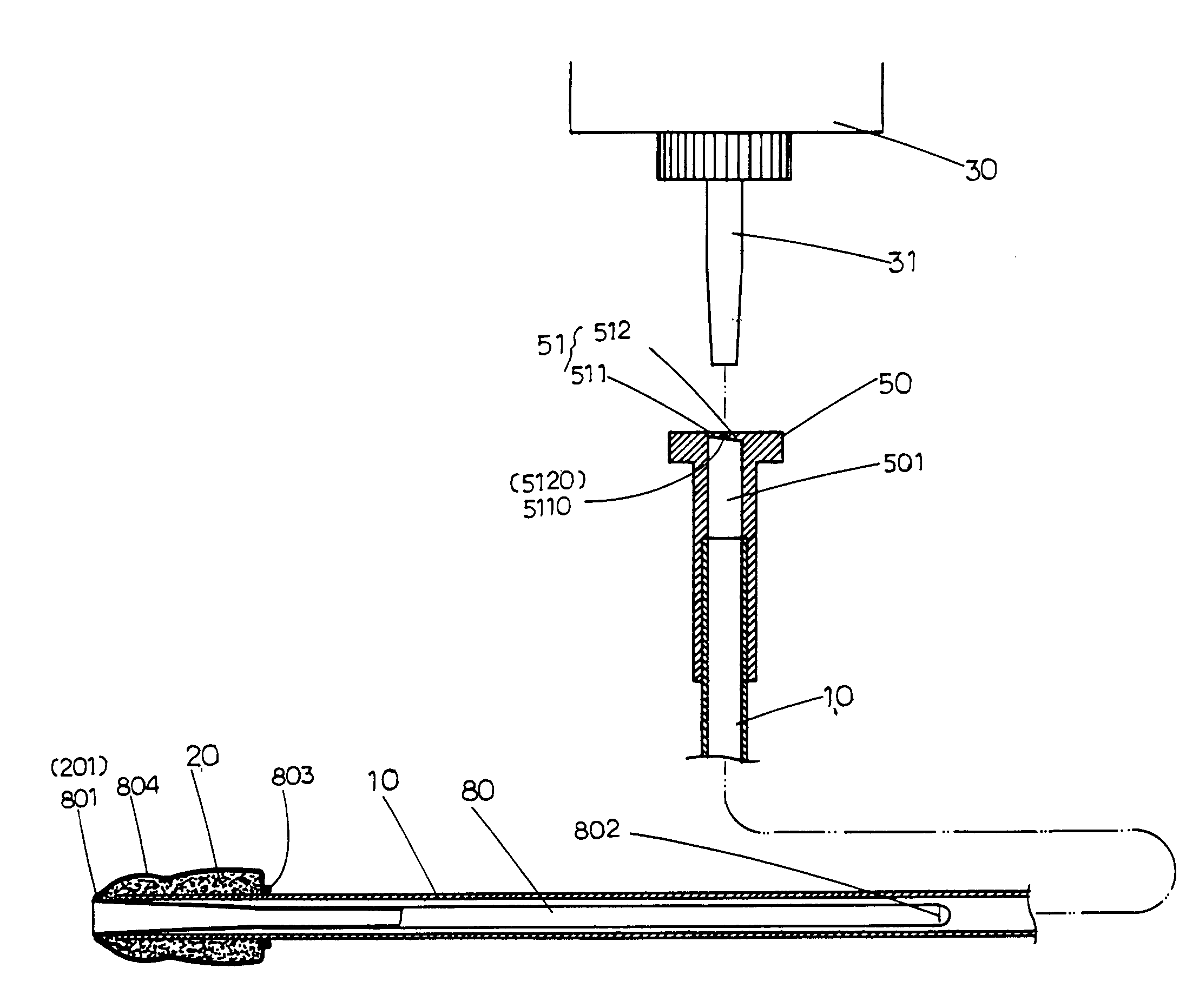
[0011] Another objective of the invention herein is to provide an improved animal-use artificial inseminator in which a connector at the rear extremity of the said insemination tube has a check membrane such that after the semen bottle insertion tube injects semen into the insemination tube insemination sheath, the said check membrane automatically opens and closes with the contractions of the womb, thereby preventing the occurrence of semen backflow and leakage, while automatically admitting air to effectively increase semen flow efficiency.

Problems solved by technology

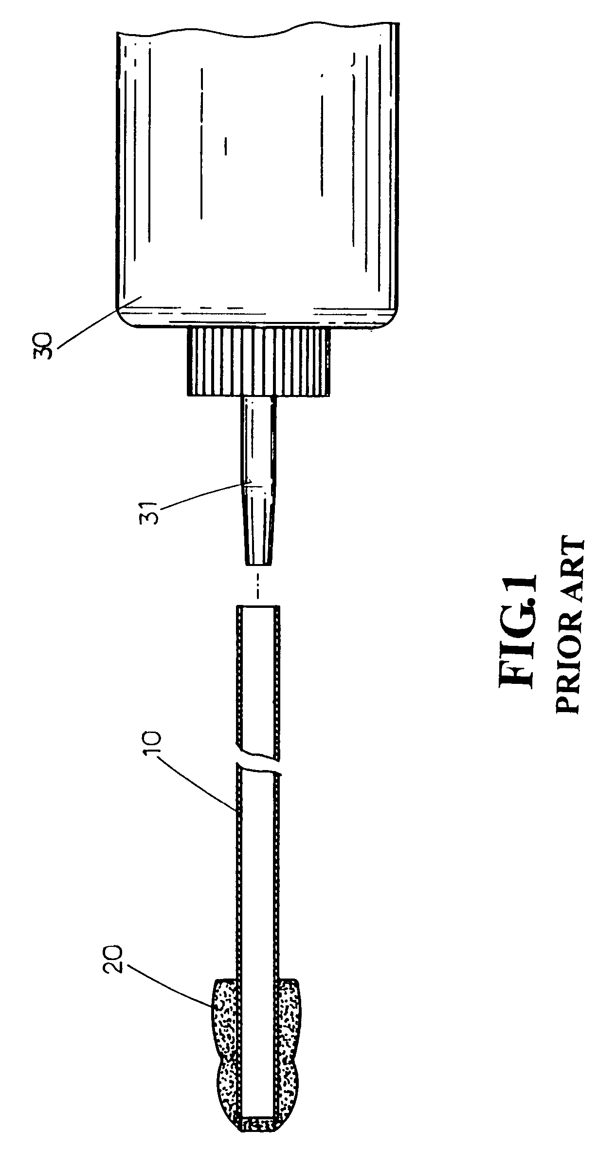
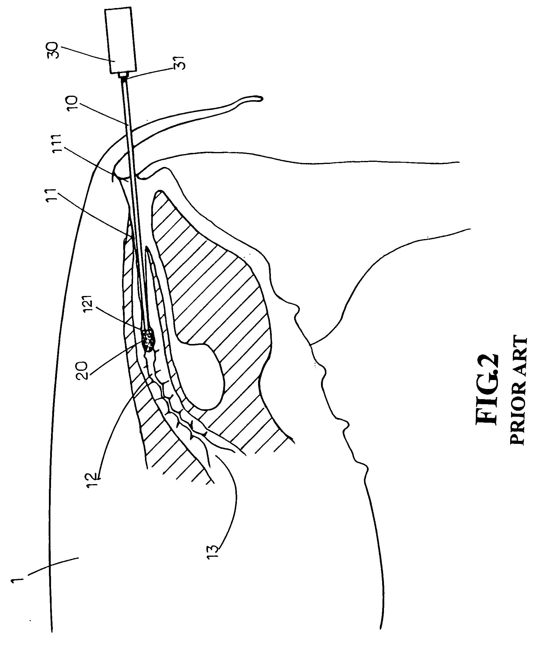
However, existent shortcomings that have not been improved include semen backflow that wastes semen, which is uneconomical and lowers insemination success rate; the easy inflow of contaminants from the outside of the female animal body into the vagina, cervix, and womb that endanger the health of the female animal and young carried in the womb; and the requiring of specialized personnel for operation, which is uneconomical and involves additional manpower.

Method used


Image

  • Animal-use artificial inseminator
  • Animal-use artificial inseminator
  • Animal-use artificial inseminator

Examples


Embodiment Construction

[0032] Referring to FIG. 5, FIG. 6, FIG. 7, FIG. 8, FIG. 9, FIG. 10, and FIG. 11, the improved animal-use artificial inseminator of the invention herein is comprised of an insemination tube 10 with a nozzle 20 at its front extremity into which an insemination sheath 80 is inserted, and a connector 50 at the rear extremity of the insemination tube 10 having a check membrane 51 that tightly closes a diverting passage 501, wherein:

[0033] The said insemination sheath 80 is a thin-membrane casing fabricated using a process and material similar to that involved in the production of balloons and condoms such that it possesses softness and elastic stretch characteristics; a first protruding ring 801 is unitarily formed near the rear end, the dimensions of the said first protruding ring 801 based on insertability into the nozzle 20 aperture 201; slits 802 (see FIG. 7) are juxtaposed along the two sides of the front end, with the diameter from the said front end to the first protruding ring ...


PUM


Abstract

An improved animal-use artificial inseminator comprised of an insemination tube with a nozzle at its front extremity into which an insemination sheath is inserted and a connector at the rear extremity of the insemination tube having a check membrane. After the insemination tube penetrates the female animal body vagina and the front end of the nozzle is nominally at the first cervical ring of the cervix, the semen bottle insertion tube is utilized to pierce the connector check membrane at the rear extremity of the insemination tube and when the semen at the insemination tube is squeezed, semen is automatically squeezed out of the insemination sheath. The soft insemination sheath proceeds along the cervix without the occurrence of friction, the front end smoothly moving forward until it reaches the position of the womb. Contractions of the womb are utilized to articulate the insemination sheath such that the contained semen is ejaculated into the two Fallopian tubes or the womb from the slits along the two sides of the front end. At the same time, after the semen bottle is pulled out, since the connector check membrane automatically opens and closes along with the contraction of the womb, not only is the semen in the insemination sheath prevented from backflow or leakage, but air is admitted for smooth and complete squeezing into the Fallopian tubes or the womb.

Description

BACKGROUND OF THE INVENTION [0001] 1) Field of the Invention [0002] The invention herein relates to an improved animal-use artificial inseminator, specifically a kind that is of a simple arrangement, easy to utilize, convenient, and enables animal semen to be rapidly and, furthermore, efficiently deposited into the two Fallopian tubes or the womb, significantly raising artificial insemination success rate and saving artificial insemination-use animal semen. Fully realizing the use of minimal amounts of insemination semen and the resulting economic benefit, the invention herein also enables safer, more hygienic, and more ergonomic artificial insemination. As such, the present invention is practical, ideal, and progressive. Furthermore, such an improved animal-use artificial inseminator is unprecedented. [0003] 2) Description of the Prior Art [0004] Prior art animal-use artificial inseminator arrangements and operation, as indicated in FIG. 1 and FIG. 2, are typically comprised of a p...

Claims


Application Information

Patent Timeline
IPC IPC(8): A61B17/43
CPCA61D19/027A61D19/028
Inventor CHEN, SHENG-JUI
Owner CHEN SHENG JUI
Learn More