Systems and methods for real time tracking of targets in radiation therapy and other medical applications

a technology of radiation therapy and target tracking, applied in the field of radiation therapy systems, can solve the problems of increasing the potential for complications of healthy tissues, moving the target often within the patient, and not being a desirable solution

Inactive Publication Date: 2006-04-13
VARIAN MEDICAL SYSTEMS
View PDF57 Cites 66 Cited by
  • Summary
  • Abstract
  • Description
  • Claims
  • Application Information

AI Technical Summary

Problems solved by technology

Increasing the radiation dose, however, also increases the potential for complications to healthy tissues.
One difficulty of radiation therapy is that the target often moves within the patient either during or between radiation sessions.
This is not a desirable solution because the larger treatment margins may irradiate a larger volume of normal tissue.
Another challenge in radiation therapy is accurately aligning the tumor with the radiation beam.
Conventional setup procedures using external marks are generally inadequate because the target may move relative to the external marks between the patient planning procedure and the treatment session and/or during the t

Method used


Image

  • Systems and methods for real time tracking of targets in radiation therapy and other medical applications
  • Systems and methods for real time tracking of targets in radiation therapy and other medical applications
  • Systems and methods for real time tracking of targets in radiation therapy and other medical applications

Examples


example

Overview

[0138] An experimental phantom based study was conducted to determine effectiveness of this system for real-time tracking. In this experiment, a custom 4D stage was constructed to allow arbitrary motion in three axes for speeds up to 10 cm / sec in each dimension, with accuracy to 0.3 mm. Position accuracy was measured by a 3D digitizing arm attached to the stage system. As shown in FIG. 21, two ellipses were created with peak to peak motion of 2 cm, 4 cm and 2 cm; and 1 cm by 2 cm and 1 cm in the x, y and z direction respectively. Three periods were used to correspond to 15, 17 and 20 breaths per minute. A single transponder was used with an integration time of 33 ms, 67 ms and 100 ms and two transponders were used with integration times of 67 ms and 100 ms. The transponders were placed in a custom phantom mounted to the 4D stage. The experiment was performed with the isocenter placed 14 cm from the AC magnetic array to simulate the position of an average lung cancer patien...

experiment summary

[0139] As shown in FIG. 22, the root mean square (RMS) error was less than 1 mm for each ellipse, period and transponder integration time. The system was able to track points throughout the path of the ellipse, for example, in a trajectory of a large ellipse moving at 17 breaths per minute. FIG. 23 is a histogram of localization errors illustrating that the range of error was low for each point measured. As shown in FIG. 24, the RMS error was higher in areas of increased velocity in most trajectories. With respect to this experiment, a single transponder system performed slightly better than dual transponder systems, with the best system being a single transponder with a 67 ms integration time.


PUM


Abstract

Systems and methods for tracking targets in real time for radiation therapy and other applications. In one embodiment, a method includes collecting position information of a marker implanted within a patient at a site relative to the target at a time tn, and providing an objective output indicative of the location of the target based on the position information collected at time tn. The objective output is provided to a memory device, user interface, and/or radiation delivery machine within 1 ms to 2 seconds of the time tn when the position information was collected. This embodiment of the method can further include providing the objective output at a periodicity of 10-200 ms during at least a portion of a treatment procedure. For example, the method can further include generating a beam of ionizing radiation and directing the beam to a machine isocenter, and continuously repeating the collecting procedure and the providing procedure every 10-200 ms while irradiating the patient with the ionizing radiation beam.

Description

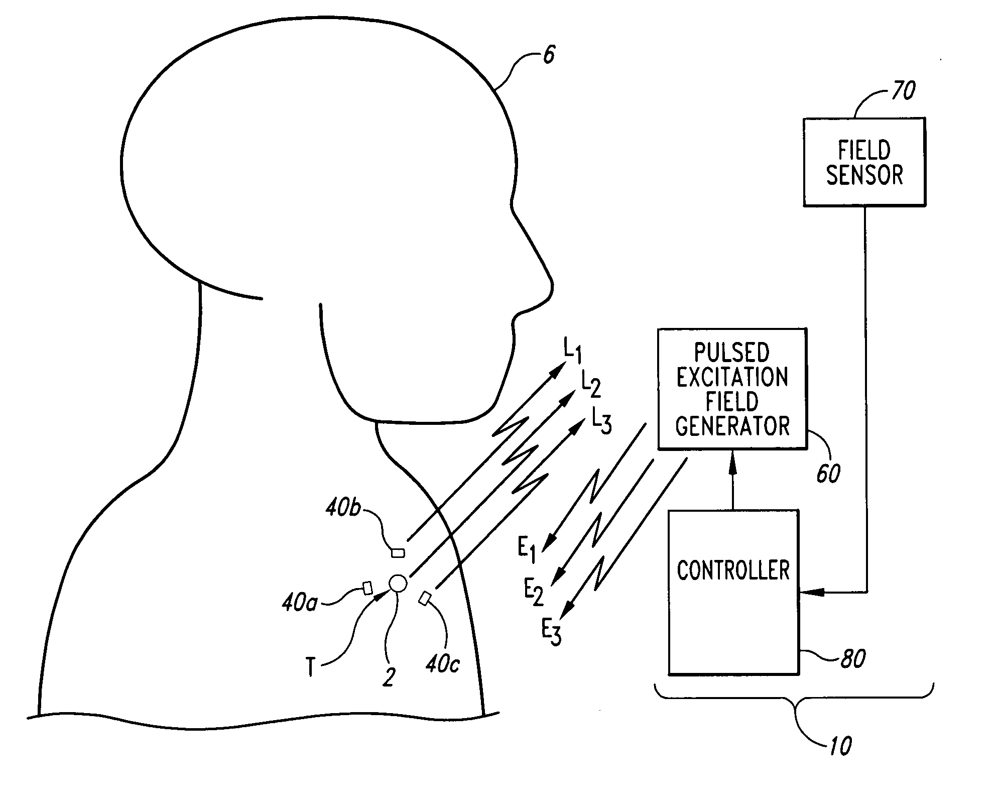
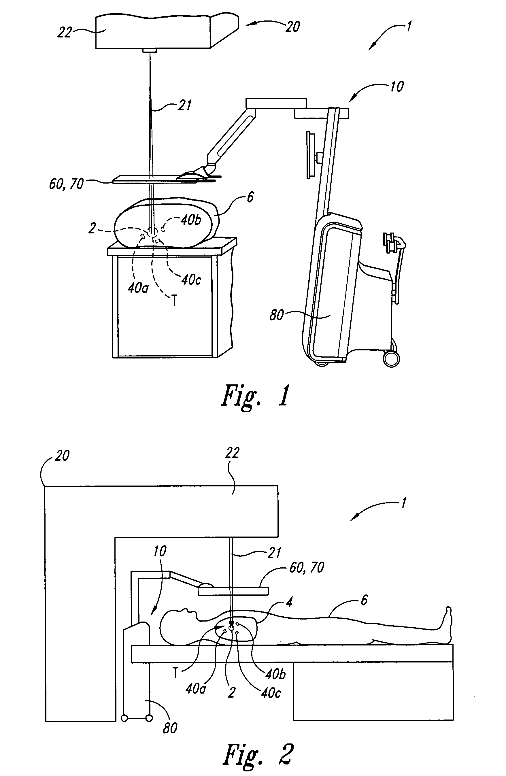
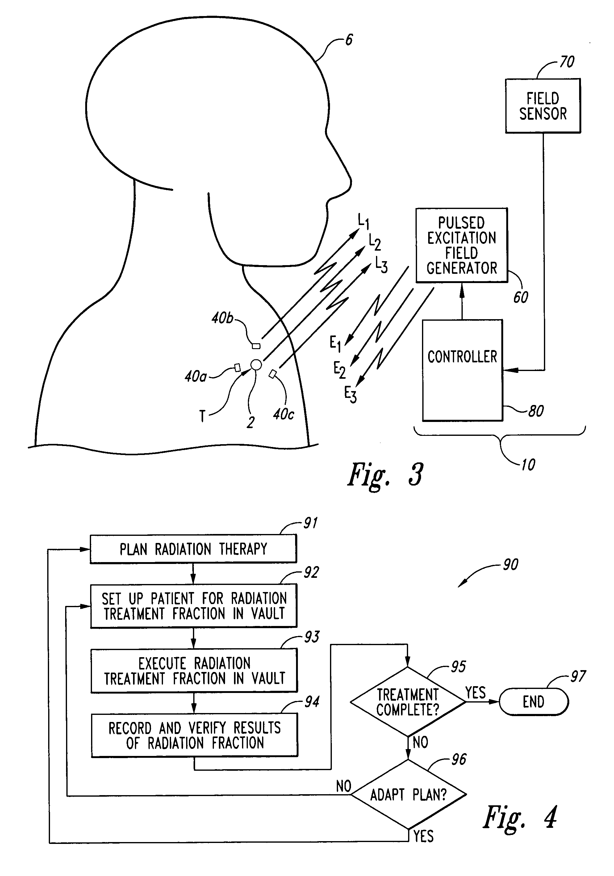
CROSS-REFERENCE TO RELATED APPLICATIONS [0001] The present application claims the benefit of U.S. Provisional Application No. 60 / 610,509 filed on Sep. 16, 2004, and U.S. Provisional Application No. 60 / 590,894 filed on Jul. 23, 2004, both of which are incorporated herein by reference in their entireties.TECHNICAL FIELD [0002] This invention relates generally to radiation therapy systems, and more particularly to systems and methods for accurately locating and tracking a target in real time for guiding and assessing radiation therapy. The invention, however, is also useful in other medical applications. BACKGROUND OF THE INVENTION [0003] Radiation therapy has become a significant and highly successful process for treating prostate cancer, lung cancer, brain cancer and many other types of localized cancers. Radiation therapy procedures generally involve (a) planning processes to determine the parameters of the radiation (e.g., dose, shape, etc.), (b) patient setup processes to position...

Claims


Application Information

Patent Timeline
IPC IPC(8): A61B6/00
CPCA61B5/055A61B5/06A61B6/12A61B8/0833A61B19/52A61B19/5244A61B19/54A61B19/56A61B2019/5251A61B2019/5408A61B2019/5454A61B2019/5458A61B2019/5495A61B2019/562A61N5/1049A61N5/1067A61N5/107A61N2005/1051A61B34/20A61B34/25A61B90/36A61B90/39A61B2034/2051A61B2034/252A61B2090/3908A61B2090/3954A61B2090/3958A61B2090/3995
Inventor WRIGHT, J. NELSONDIMMER, STEVEN C.
Owner VARIAN MEDICAL SYSTEMS
Why Eureka
Try Eureka