Eureka AIR delivers breakthrough ideas for toughest innovation challenges, trusted by R&D personnel around the world.

Urinal outlet assembly

Inactive Publication Date: 2006-04-20
MCALPINE
View PDF3 Cites 4 Cited by
  • Summary
  • Abstract
  • Description
  • Claims
  • Application Information

AI Technical Summary

Benefits of technology

[0012] In use, the connector may be coupled to a waste pipe inlet by any appropriate means. The urinal outlet pipe may then be slid into the connector. The provision of a sliding sealing fit between the connector and the outlet pipe provides a degree of flexibility in the relative axial location of the connector and the urinal, such that the location of the connector, and thus the waste pipe inlet, becomes less critical than in conventional coupling arrangements. Also, the provision of the sliding sealing fit facilitates making up of the connection; in a preferred embodiment, all that is required is for the end of the outlet pipe to be located in the open end of the connector and the urinal then moved rearwards to push the outlet pipe into the connector. Once the end of the outlet pipe has been correctly located in the open end of the connector an operator involved in fitting the urinal may then concentrate on other matters, such as correctly and securely mounting the urinal on the supporting wall.
[0015] Preferably, the connector is adapted to engage with, but need not be a tight fit on, the waste pipe inlet. This facilitates making up the connection between the connector and the waste pipe inlet, and is particularly useful when the connection is relatively inaccessible, for example within a wall opening. The end of the connector may be adapted to be received in the waste pipe inlet, or may be adapted to receive the waste pipe inlet. The connector may be adapted to be solvent welded, glued or otherwise permanently fixed to the waste pipe.

Problems solved by technology

Furthermore, the coupling of the trap outlet pipe to the waste pipe inlet is problematic, given that the coupling location is within the wall and is intentionally concealed behind the trap and the urinal.

Method used


Image

  • Urinal outlet assembly
  • Urinal outlet assembly

Examples


Embodiment Construction

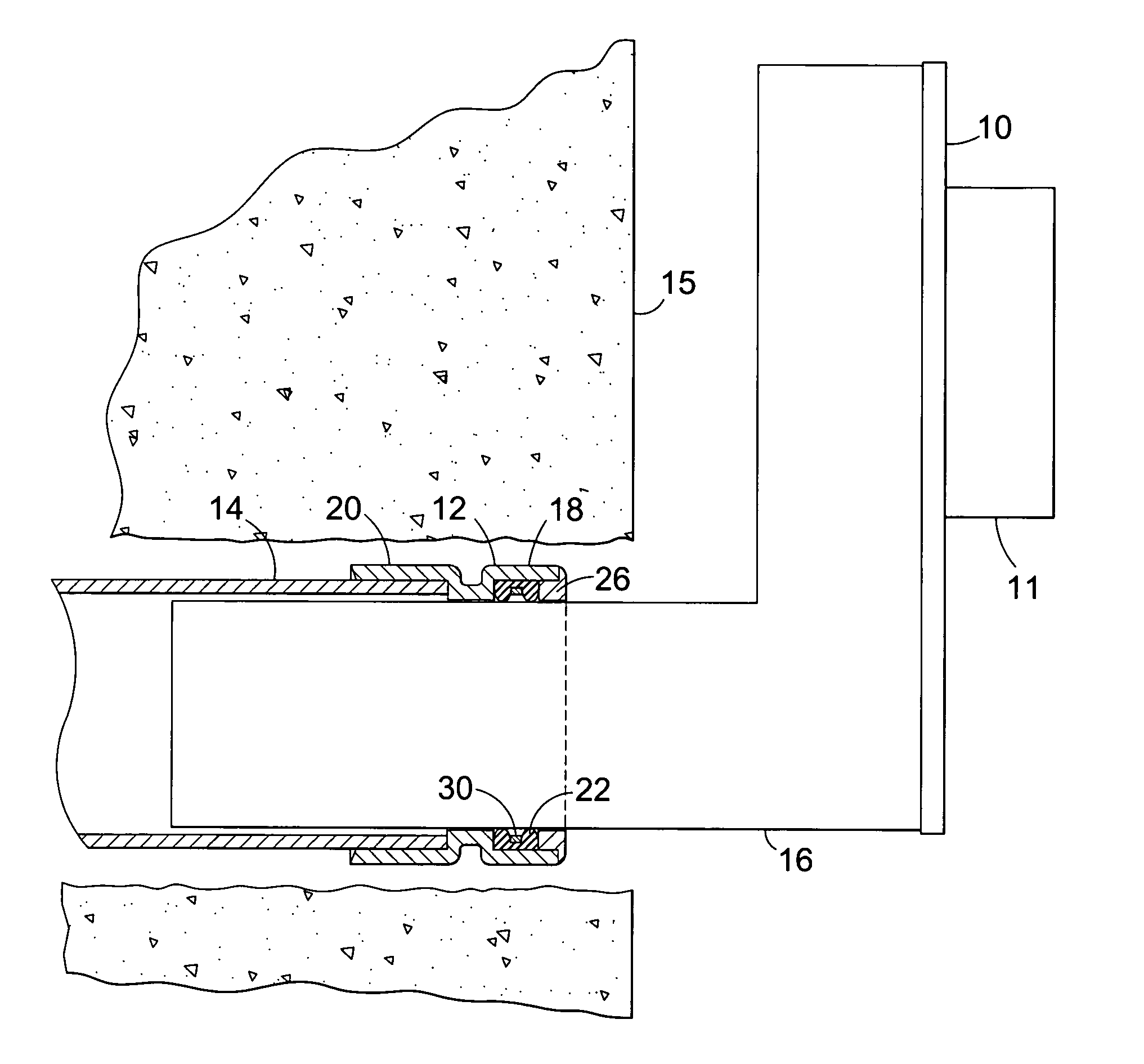
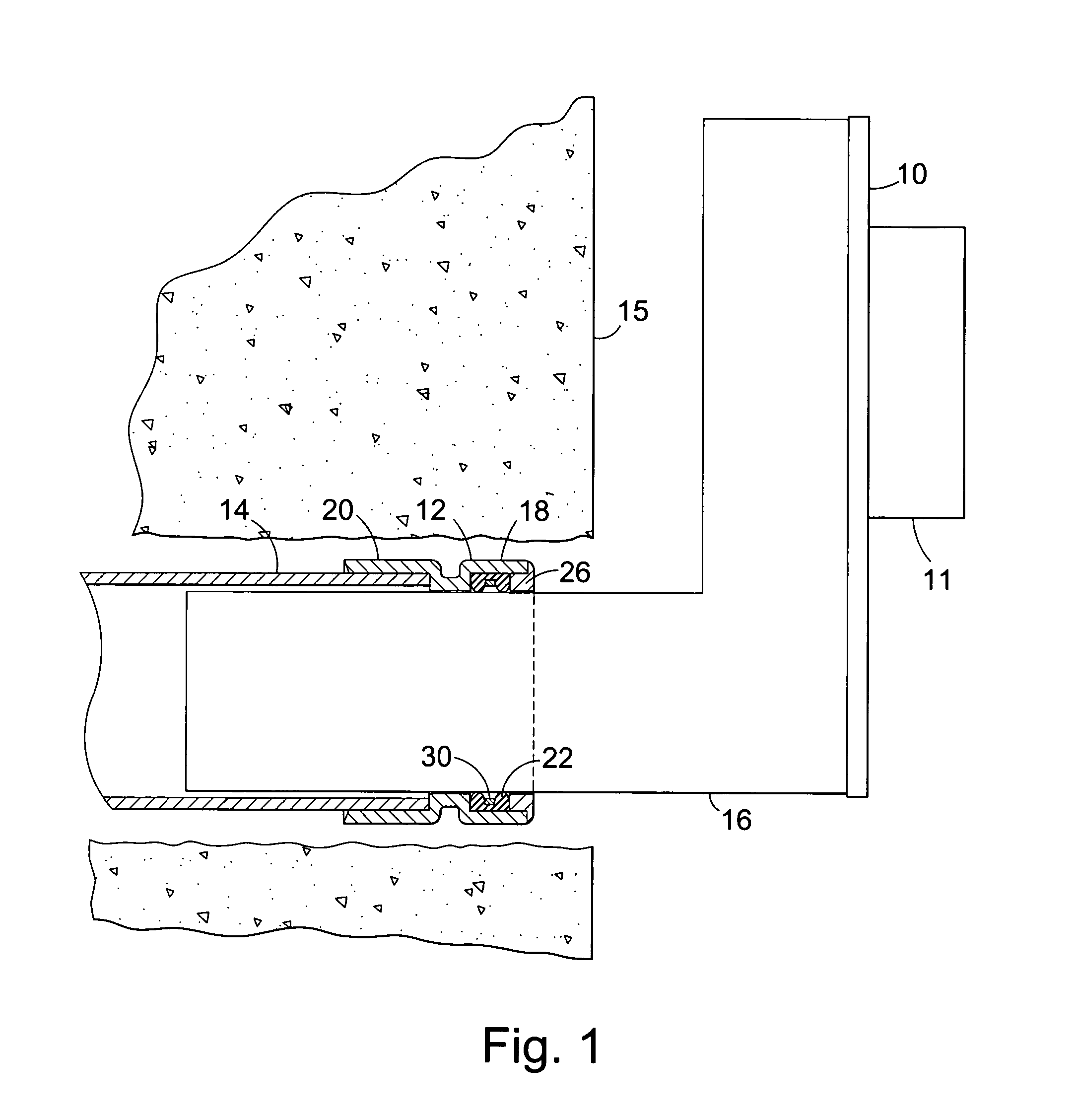
[0020] The drawing shows a part sectional view of a urinal trap assembly, including a urinal trap 10 (not shown in section). The urinal trap 10 features a tubular inlet 11 which is normally fitted with an elastomer seal (not shown) which allows the inlet 11 to be fitted over the outlet formed in the rear of a urinal (not shown). A connector 12 is provided for coupling the trap 10 to a waste pipe inlet 14. The waste pipe inlet 14 is shown located in an opening in a wall 15 which contains concealed pipe work.

[0021] The trap 10 features an outlet pipe in the form of a horizontal constant diameter tube 16.

[0022] The connector 12 is generally tubular and includes an inlet portion 18 for receiving the trap outlet pipe 16, and an outlet portion 20 for receiving the waste pipe inlet 14. In this embodiment, the connector 12 is adapted to be glued or solvent welded to the waste pipe inlet 14 to create a permanent coupling. However, the inlet portion 18 is intended to receive the trap outlet...


PUM


Abstract

A urinal outlet assembly comprises a urinal outlet pipe and a connector for coupling the outlet pipe to a waste pipe inlet. The connector is adapted to receive the outlet pipe in a sliding sealing fit.

Description

[0001] This present application claims all available benefit, under 35 U.S.C. §119(b), of Utility Patent Application No. GB0422136.2, filed in the United Kingdom on Oct. 6, 2004. FIELD OF THE INVENTION [0002] This invention relates to a urinal outlet assembly, and to a connection for coupling a urinal outlet to a waste pipe. BACKGROUND OF THE INVENTION [0003] Conventionally, the waste pipe leading from a urinal is coupled to the soil pipe system via exposed plumbing, that is piping and water traps which are visible to a washroom user. However, there is increasing demand for the provision of urinals in which the plumbing is concealed. [0004] In one arrangement a “low profile” water trap is concealed within a recess in the rear face of the urinal. Such water traps feature a hollow body having a centrally located inlet in a front face, which inlet is provided with a seal arrangement and connects directly to the urinal outlet. The trap outlet pipe extends from a lower part of the body a...

Claims


Application Information

Patent Timeline
IPC IPC(8): E03D13/00E03D11/14F16L27/12
CPCE03D11/14F16L27/12E03D13/00
Inventor MCALPINE, JAMES EDWARD
Owner MCALPINE
Why Eureka
Eureka Blog
Learn More