Vapor compression refrigerating apparatus
a refrigerating apparatus and vapor compression technology, applied in the direction of lighting and heating apparatus, machine operation mode, transportation and packaging, etc., can solve the problems of shortening the heating source of the heater, insufficient amount of waste heat, and inability to supply the engine to the heater as the heating source, so as to achieve the effect of effectively using waste heat and deficit of heat energy
- Summary
- Abstract
- Description
- Claims
- Application Information
AI Technical Summary
Benefits of technology
Problems solved by technology
Method used
Image

Examples
first embodiment
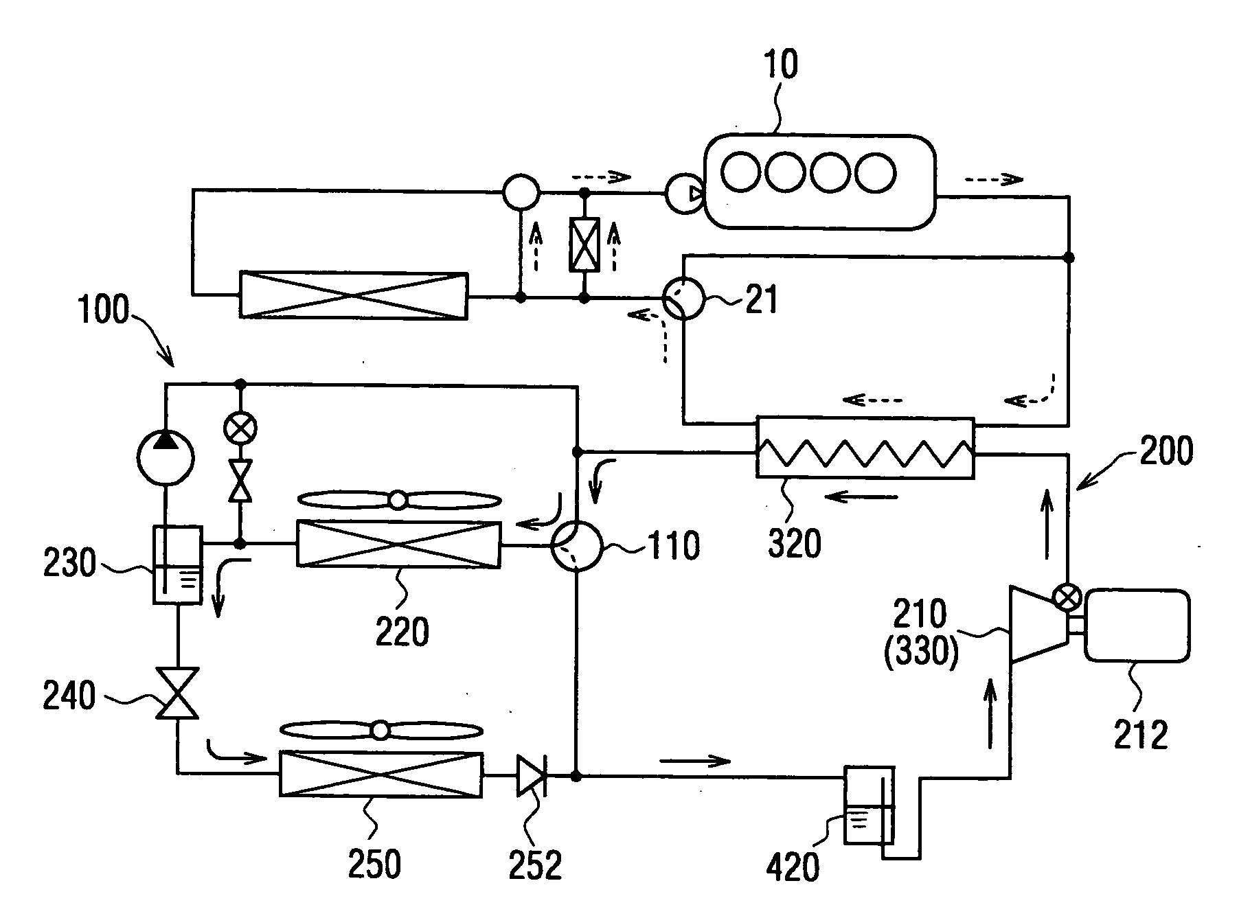
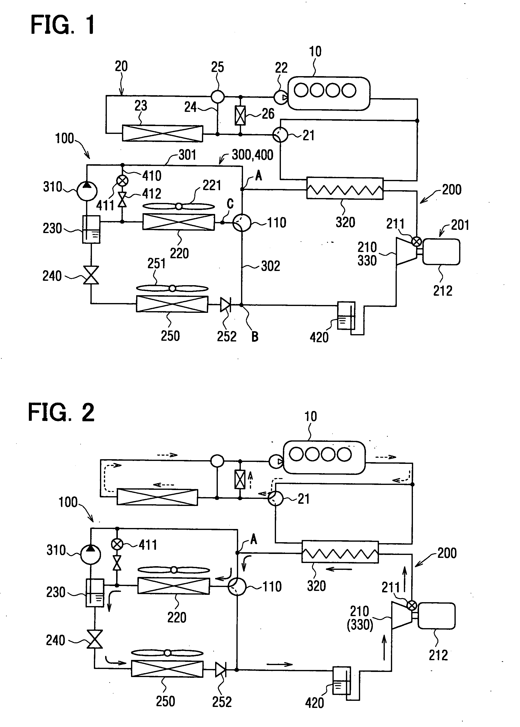
[0022] A first embodiment of the present invention is a vapor compression refrigerating apparatus 100, which is applied to a water cool type engine 10 (an internal combustion engine). The engine 10 corresponds to a heat generating apparatus generating waste heat as a result of controlling an operational temperature of the heat generating apparatus.
[0023] The vapor compression refrigerating apparatus 100 (hereinafter, simply referred to as the refrigerating apparatus) comprises a well known refrigerating cycle 200, into which Rankine cycle 300 and a heat pump cycle 400 are incorporated.
[0024] A compressor device 210 is provided in the refrigerating cycle 200, for sucking refrigerant and compressing the same to high temperature and high pressure refrigerant, wherein the compressor device 210 is formed as an expansion-compressor device 201, which is also used as an expansion device 330 for the Rankine cycle 300. The compressor device 210 (the expansion device 330) is, for example, co...
second embodiment
[0062] A second embodiment of the present invention is shown in FIG. 6, which differs from the first embodiment in that the condenser 220 is modified. More specifically, the condenser is formed as a sub-cool condenser device 220a, which comprises the (main) condenser 220, a gas-liquid separator 230, and a sub-cool condenser 231. The gas-liquid separator 230 and the sub-cool condenser 231 are arranged at a refrigerant outlet side of the condenser 220 in case of the operation of the Rankine cycle 300. The main condenser 220, the gas-liquid separator 230, and the sub-cool condenser 231 can be formed as an integrally constructed one unit.
[0063] According to the above structure of the second embodiment, the liquid phase refrigerant, which is discharged from the condenser 220 into the gas-liquid separator 230 and separated therein, can be further cooled down by the sub-cool condenser 231. Then, the refrigerant is supplied to the liquid pump 310. Accordingly, even when the pressure at the...
third embodiment
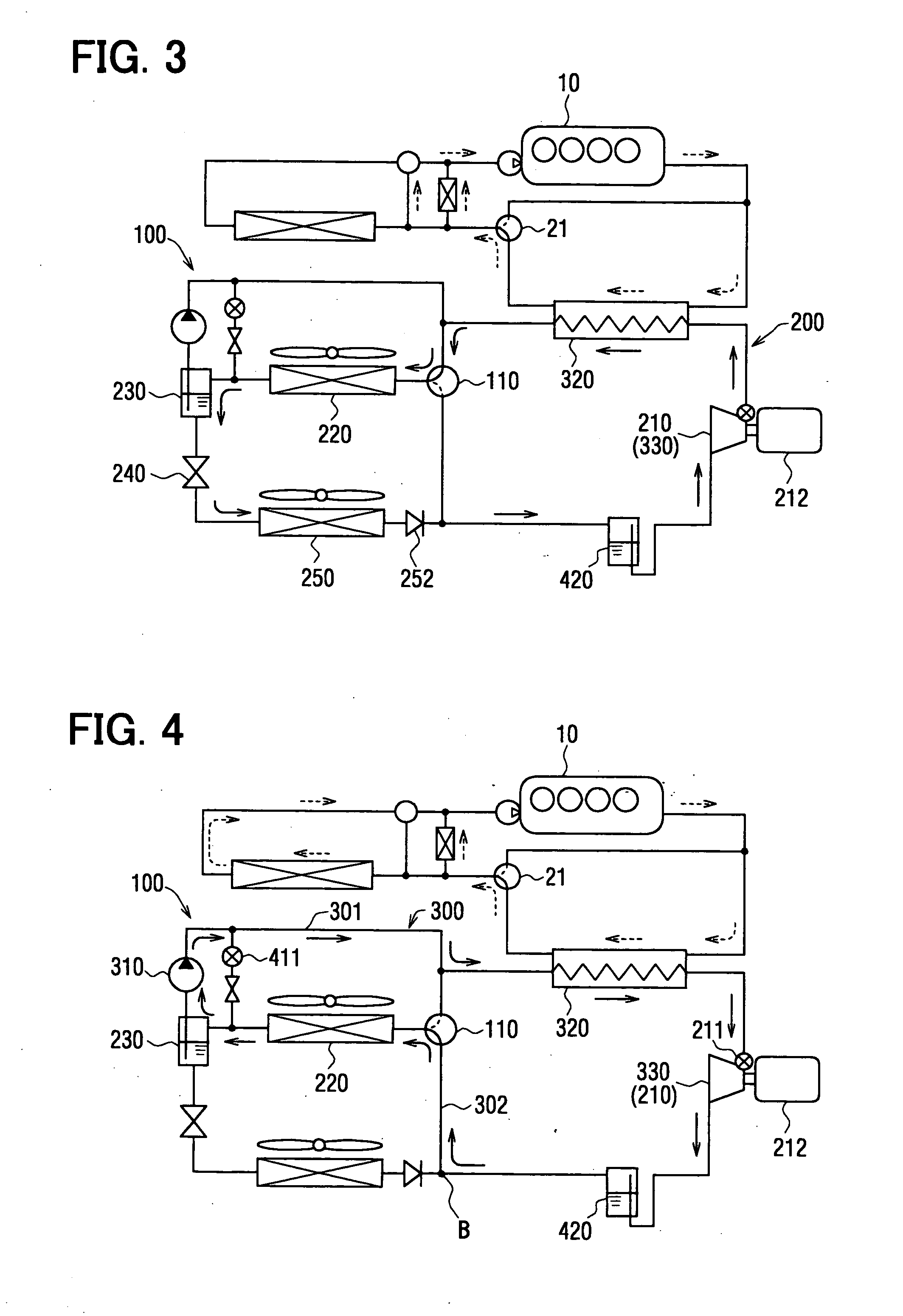
[0066] A third embodiment of the present invention is shown in FIG. 8, which differs from the first embodiment in a position of the accumulator 420.
[0067] According to the third embodiment, the accumulator 420 is arranged at such a position, which is out of refrigerant flow when the system is operated in the refrigerating cycle 200. More specifically, the accumulator 420 is arranged in the second bypass passage 302 between the switching valve 110 and the juncture B.
[0068] According to the above arrangement of the accumulator 420, the refrigerant does not flow through the accumulator 420 in case of the operation of the refrigerating cycle 200, and thereby the pressure loss can be likewise decreased.
[0069] A modification of the third embodiment is shown in FIG. 9. An accumulator bypass passage 422 is provided in order to bypass the accumulator 420, when the system is operated with the Rankine cycle 300. A check valve 421 is provided to allow the refrigerant to flow from the junctur...
PUM
 Abstract
Description
Claims
Application Information
 - R&D
- Intellectual Property
- Life Sciences
- Materials
- Tech Scout
- Unparalleled Data Quality
- Higher Quality Content
- 60% Fewer Hallucinations
Browse by: Latest US Patents, China's latest patents, Technical Efficacy Thesaurus, Application Domain, Technology Topic, Popular Technical Reports.
© 2025 PatSnap. All rights reserved.Legal|Privacy policy|Modern Slavery Act Transparency Statement|Sitemap|About US| Contact US: help@patsnap.com