Methods and systems for processing a bevel edge of a substrate using a dynamic liquid meniscus

a technology of dynamic liquid meniscus and bevel edge, which is applied in the direction of cleaning using liquids, chemistry apparatus and processes, and cleaning using tools, etc., can solve the problems of inoperable devices on the wafer, scratches on the wafer surface, and inability to meet the needs of metallization features,

Inactive Publication Date: 2006-04-20
LAM RES CORP
View PDF6 Cites 14 Cited by
  • Summary
  • Abstract
  • Description
  • Claims
  • Application Information

AI Technical Summary

Benefits of technology

[0012] The method can also include moving the edge meniscus off of the edge of the substrate. Moving the edge meniscus onto the edge of the substrate can include rotating the proximity head about an axis of the proximity head. Moving the edge meniscus onto the edge of the substrate can also include moving the meniscus relative to the edge of the substrate. Moving the edge meniscus can also include increasing the size of the edge meniscus.
[0017] Another embodiment provides a method of processing an edge of a substrate including supporting the substrate by an edge roller, the edge roller including a proximity head and forming a meniscus inside a concave portion of the proximity head. The concave portion is capable of receiving at least a portion of an edge of the substrate. The meniscus encompasses the edge of the substrate within a portion of the circumference of the substrate. The meniscus is moved onto the edge of the substrate and moved along the edge of the substrate. Moving the meniscus onto the edge of the substrate can include increasing the size of the meniscus.
[0022] The various embodiments of the present invention provide the advantage of processing an edge (e.g., cleaned, etched) of the substrate through use of an edge-shaped head that can support a meniscus around the edge of the substrate.

Problems solved by technology

Unfortunately, the CMP process tends to leave an accumulation of slurry particles and residues at the wafer surface.
If left on the wafer, the unwanted residual material and particles may cause, among other things, defects such as scratches on the wafer surface and inappropriate interactions between metallization features.
In some cases, such defects may cause devices on the wafer to become inoperable.
Unfortunately, if the moving liquid / gas interface breaks down, as often happens with all of the aforementioned drying methods, droplets form and evaporation occurs resulting in contaminants being left on the wafer surface.
As stated previously, if the moving liquid / gas interface 12 breaks down, droplets of the cleaning fluid form on the wafer and contamination may occur due to evaporation of the droplets.
Unfortunately, the present drying methods are only partially successful at the prevention of moving liquid interface breakdown.
In addition, the SRD process has difficulties with drying wafer surfaces that are hydrophobic.
Hydrophobic wafer surfaces can be difficult to dry because such surfaces repel water and water based (aqueous) cleaning solutions.
Therefore, because of the hydrophobic interactions and the surface tension, balls (or droplets) of aqueous cleaning fluid forms in an uncontrolled manner on the hydrophobic wafer surface.
This formation of droplets results in the harmful evaporation and the contamination discussed previously.
The limitations of the SRD are particularly severe at the center of the wafer, where centrifugal force acting on the droplets is the smallest.
Consequently, although the SRD process is presently the most common way of wafer drying, this method can have difficulties reducing formation of cleaning fluid droplets on the wafer surface especially when used on hydrophobic wafer surfaces.
An additional problem is that the edge of the wafer surface can be difficult to fully clean using the SRD process.

Method used


Image

  • Methods and systems for processing a bevel edge of a substrate using a dynamic liquid meniscus
  • Methods and systems for processing a bevel edge of a substrate using a dynamic liquid meniscus
  • Methods and systems for processing a bevel edge of a substrate using a dynamic liquid meniscus

Examples


Embodiment Construction

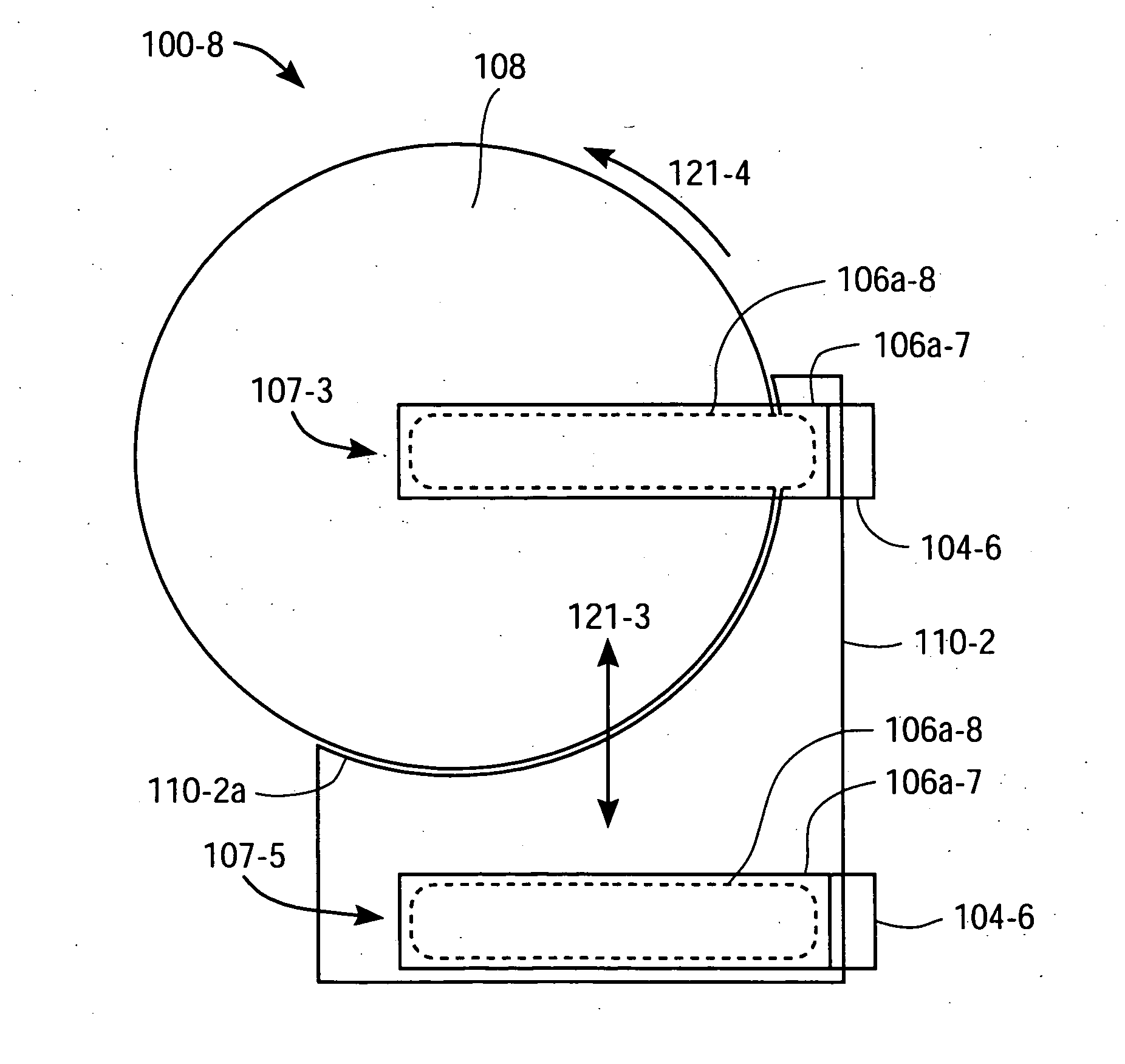
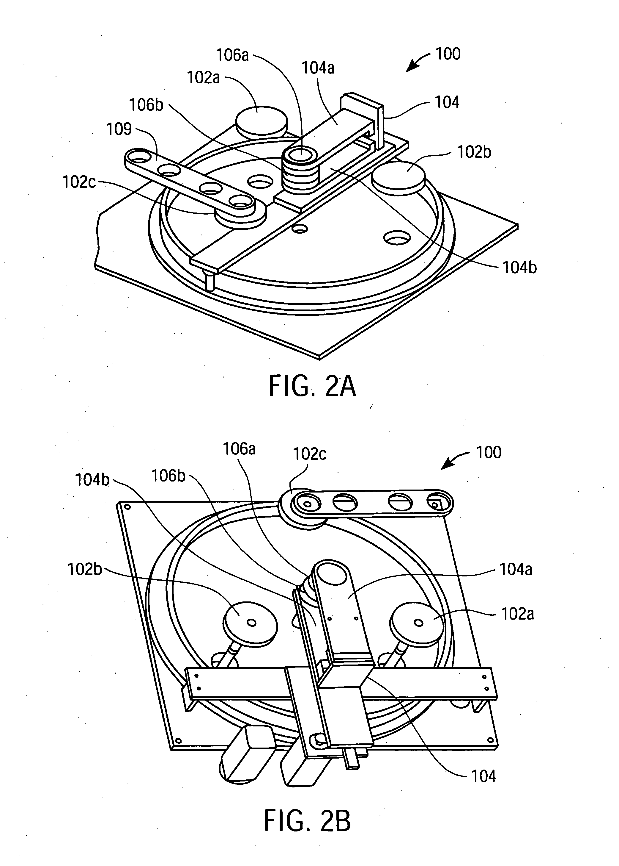
[0092] Several exemplary embodiments for methods and apparatuses for processing (e.g., cleaning, rinsing, drying, etching) an edge of a wafer will now be described. In the following description, numerous specific details are set forth in order to provide a thorough understanding of the present invention. It will be understood, however, by one of ordinary skill in the art, that the present invention may be practiced without some or all of these specific details. In other instances, well known process operations have not been described in detail in order not to unnecessarily obscure the present invention.

[0093] While this invention has been described in terms of several preferred embodiments, it will be appreciated that those skilled in the art upon reading the preceding specifications and studying the drawings will realize various alterations, additions, permutations and equivalents thereof. It is therefore intended that the present invention includes all such alterations, additions...


PUM

PropertyMeasurementUnit
sizeaaaaaaaaaa
sizeaaaaaaaaaa
diameteraaaaaaaaaa

Abstract

A system and method for processing an edge of a substrate includes an edge roller and a first proximity head. The first proximity head being mounted on the edge roller. The first proximity head capable of forming a meniscus and including a concave portion and multiple ports opening into the concave portion. The concave portion being capable of receiving an edge of a substrate and the ports including at least one process liquid injection port, at least one vacuum port and at least one surface tension control port.

Description

CROSS REFERENCE TO RELATED APPLICATIONS [0001] This application is a divisional of and claims priority from U.S. patent application Ser. No. 10 / 603,427 filed on Jun. 24, 2003 and entitled “Methods and Systems for Processing a Bevel Edge of a Substrate Using a Dynamic Liquid Meniscus” which is a continuation-in-part and claims priority from co-pending U.S. patent application Ser. No. 10 / 330,843 filed on Dec. 24, 2002 and entitled “Meniscus, Vacuum, IPA Vapor, Drying Manifold,” which is a continuation-in-part of co-pending U.S. patent application Ser. No. 10 / 261,839 filed on Sep. 30, 2002 and entitled “Method and Apparatus for Drying Semiconductor Wafer Surfaces Using a Plurality of Inlets and Outlets Held in Close Proximity to the Wafer Surfaces,” both of which are incorporated herein by reference in its entirety. The Ser. No. 10 / 603,427 application is also a continuation in part of U.S. patent application Ser. No. 10 / 330,897, filed on Dec. 24, 2002, entitled “System for Substrate Pr...

Claims


Application Information

Patent Timeline
Patent Type & Authority Applications(United States)
IPC IPC(8): C23G1/00B08B3/00B08B1/02H01L25/00B08B3/04H01L21/00
CPCB08B3/04H01L21/67028Y10S134/902H01L21/67051H01L21/67034H01L21/304H01L21/68
Inventor WOODS, CARL A.GARCIA, JAMES P.DE LARIOS, JOHN M.
Owner LAM RES CORP
Why Eureka
Try Eureka