Divided wall exchange column

a wall exchange column and wall exchange technology, applied in the direction of combustion-air/fuel-air treatment, lighting and heating apparatus, separation processes, etc., can solve the problems of significant force, serious problems, and temperature differential can cause unwanted changes

Active Publication Date: 2006-04-20
AIR PROD & CHEM INC
View PDF23 Cites 21 Cited by
  • Summary
  • Abstract
  • Description
  • Claims
  • Application Information

AI Technical Summary

Problems solved by technology

These requirements raise serious problems which must be addressed in the design and manufacture of divided wall columns.
The pressure differential can exert a significant force on the dividing wall, which must be countered by the mechanical design of the wall, and the temperature differential can give rise to an unwanted change in the distillation process adjacent to the dividing wall, which must be countered by some form of thermal resistance (insulation) between the two sides.
Prior art designs for countering such force are difficult and / or expensive to manufacture, often lead to an unacceptable loss in the column area available for distillation, or substantially interfere with the distillation process.
Another problem is that the prior art does not satisfactorily address how to design the layout of structured packing and / or trays in divided wall columns or, in the case of structured packing, how to design and arrange the liquid distributor.
However, although the thickness of the sheet can be increased, the increase in strength obtained is relatively poor, especially at large column diameters.
Moreover, if the thickness of the chord wall is too dissimilar to that of the outer wall, there are complications associated with the welding of the chord wall to the column wall, as well as simply occupying a greater portion of the column area.
True honeycomb walls and laminated walls are difficult and expensive to manufacture, although such walls do provide the benefit of higher thermal resistance if that is required.
For example, welding ribs to a wall tends to be expensive, since welding can distort a flat sheet, especially if the ribs must be attached only to one side.
Also, if ribs are used in a packed column, the ribs may intrude into the structured packing and cause problems both with the installation of the packing and / or the distillation process.
In the case of a preassembled stack of self-supporting trays being installed in a column, strengthening ribs on a dividing wall may intrude into the area where the tray stack is to be installed, leading to greater difficulty in installation; additionally, the trays may rest on the ribs when the column is lying on its side for manufacture or transportation and thereby be distorted, as well as cause problems with the distillation process.

Method used


Image

  • Divided wall exchange column
  • Divided wall exchange column
  • Divided wall exchange column

Examples


Embodiment Construction

[0058] The present invention is discussed herein in the context of divided wall exchange columns used for air separation processes. Persons skilled in the art will recognize, however, that the invention may be utilized in other processes which use divided wall exchange columns.

[0059] In modern air separation plants, structured packing is most often used as the preferred mass transfer device, although trays may still be used in specific circumstances for specific applications. For some applications, structured packing may be used on one side of the dividing wall, while trays are used on the other side of the dividing wall.

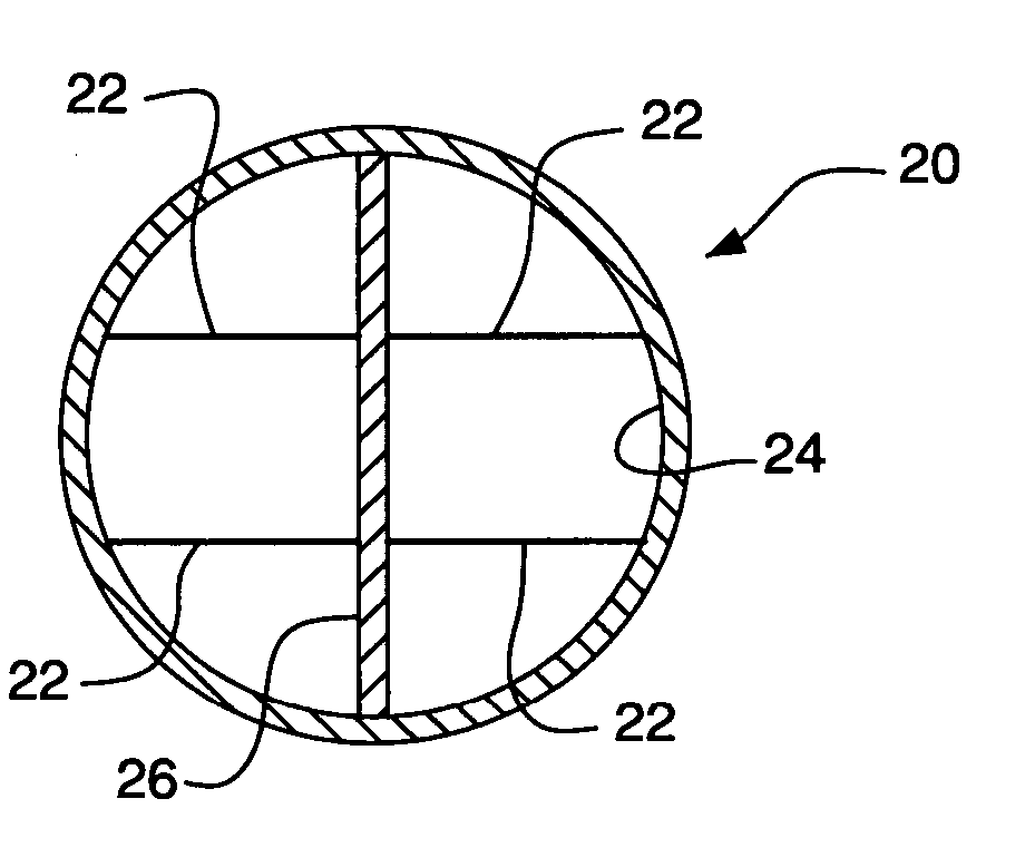
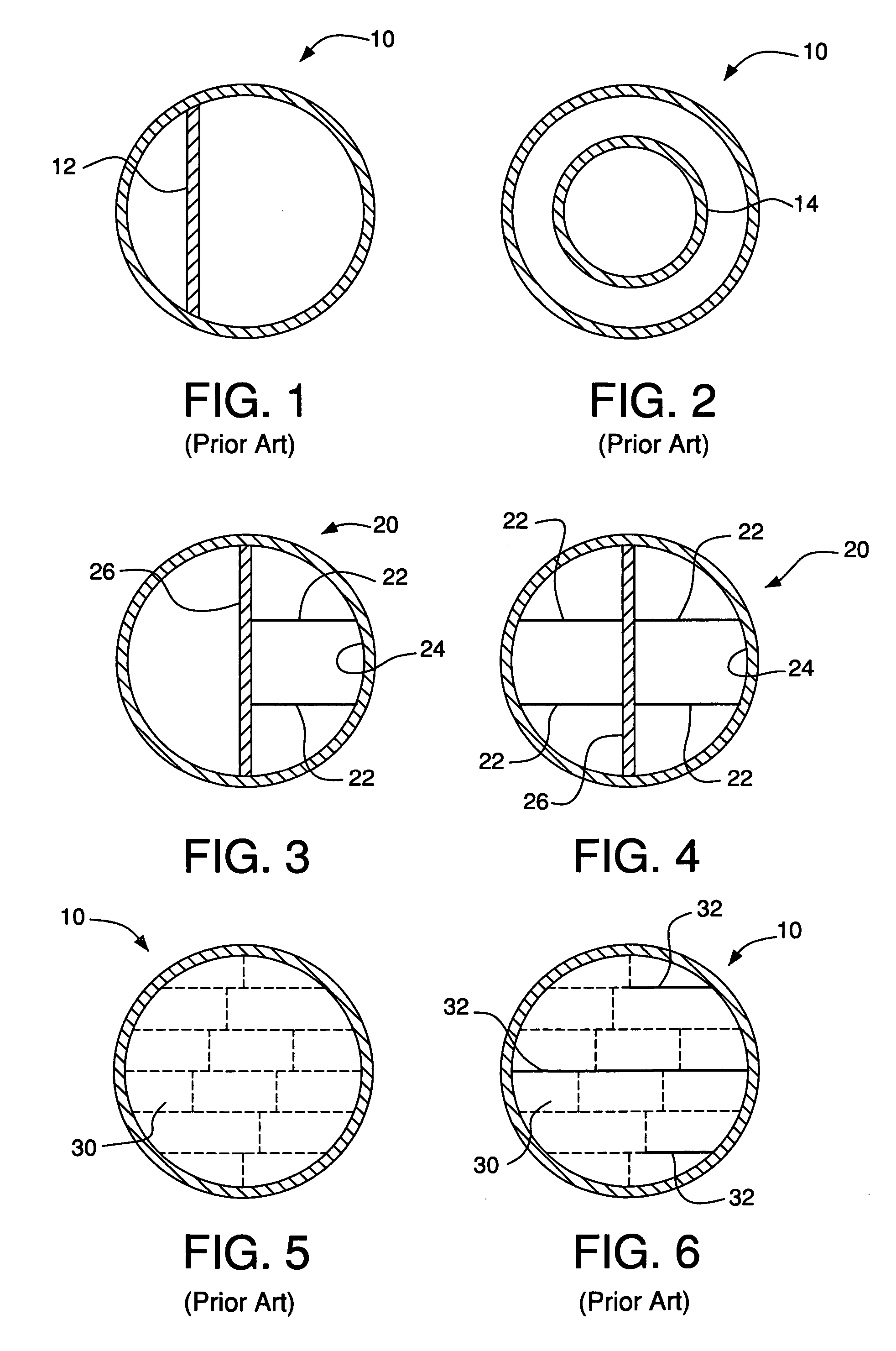
[0060] One embodiment of an exchange column 20 using the present invention is shown in FIG. 3 where one end of a stiffening member 22, such as a tie-bar, is connected to the inner wall 24 of the column and the other end of the stiffening member is connected to the dividing wall 26 to stiffen the dividing wall. More than one stiffening member (e.g., tie-bar), as sh...


PUM

PropertyMeasurementUnit
rotated angleaaaaaaaaaa
angleaaaaaaaaaa
angleaaaaaaaaaa

Abstract

A divided wall exchange column includes a dividing wall strengthened by stiffening members and / or a double wall design to better withstand pressure differentials and minimize temperature differentials. When a double wall is used, cost of manufacture and installation is minimized by reducing the manufacturing tolerances required while providing a design robust in construction, installation, and operation. When structured packing is used, the stiffening members, combined with positioning the layers of packing at preferred angles relative to the dividing wall, result in minimal interference with the heat and / or mass transfer process while minimizing the complexity of manufacture and construction of the packing. Further, by positioning the top layer of structured packing at other preferred angles relative to the dividing wall, a simplified liquid distributor design may be used in the divided wall exchange column while the layers below may still be orientated as described above with all the associated benefits.

Description

BACKGROUND OF THE INVENTION [0001] The present invention relates to divided wall exchange columns for heat and / or mass transfer processes. The invention has particular application in cryogenic air separation processes utilizing distillation, although it also may be used in other heat and / or mass transfer processes which use trays and packing (e.g., random or structured packing). [0002] As used herein, the term “column” (or “exchange column”) means a distillation or fractionation column or zone, i.e., a column or zone where liquid and vapor phases are countercurrently contacted to effect separation of a fluid mixture, such as by contacting of the vapor and liquid phases on packing elements or on a series of vertically-spaced trays or plates mounted within the column. [0003] The term “column section” (or “section”) means a zone in a column filling all or part of a cross section of the column. The top or bottom of a particular section or zone ends at the liquid and vapor distributors (...

Claims


Application Information

Patent Timeline
Patent Type & Authority Applications(United States)
IPC IPC(8): B01F3/04
CPCB01D3/14B01D3/141B01J19/32B01J19/325B01J2219/32213B01J2219/32268B01J2219/32272B01J2219/32275F25J3/04927F25J3/04939B01D15/00
Inventor ZONE, IAN ROBERTCHALK, CLIVEKOVAK, KENNETH WILLIAMSUNDER, SWAMINATHAN
Owner AIR PROD & CHEM INC
Why Eureka
Try Eureka