Rack level power management

a power management and rack technology, applied in emergency power supply arrangements, instruments, data switching details, etc., can solve the problems of increased temperature of supply, inefficient small power supply multiplicity, waste of energy, etc., and achieve the effect of reducing power consumption

Inactive Publication Date: 2006-04-20
NEVERMORE SOLUTIONS
View PDF21 Cites 169 Cited by
  • Summary
  • Abstract
  • Description
  • Claims
  • Application Information

AI Technical Summary

Benefits of technology

[0013] In one embodiment, the power manager of at least one power managed module may sense a change in a voltage level from the at least one power source, and in re

Problems solved by technology

A module which is utilizing only a small amount of energy, such as when the module is off or in a standby mode, still consumes and wastes energy.
Furthermore, a multiplicity of independent small power supplies is inefficient, with supply begins to exhibit an increased temperature.
This increase in temperature leads to a shortened life for the power supply.
Thus, certain modules in the rack may experience early failure due to power supply stress, while neighboring modules may be operating at low utilization rates.
The dedicated additional power source is typically initially underutilized, and only experiences optimum utilization as the system power needs grow.
This underutilized dedicat

Method used


Image

  • Rack level power management
  • Rack level power management
  • Rack level power management

Examples


first embodiment

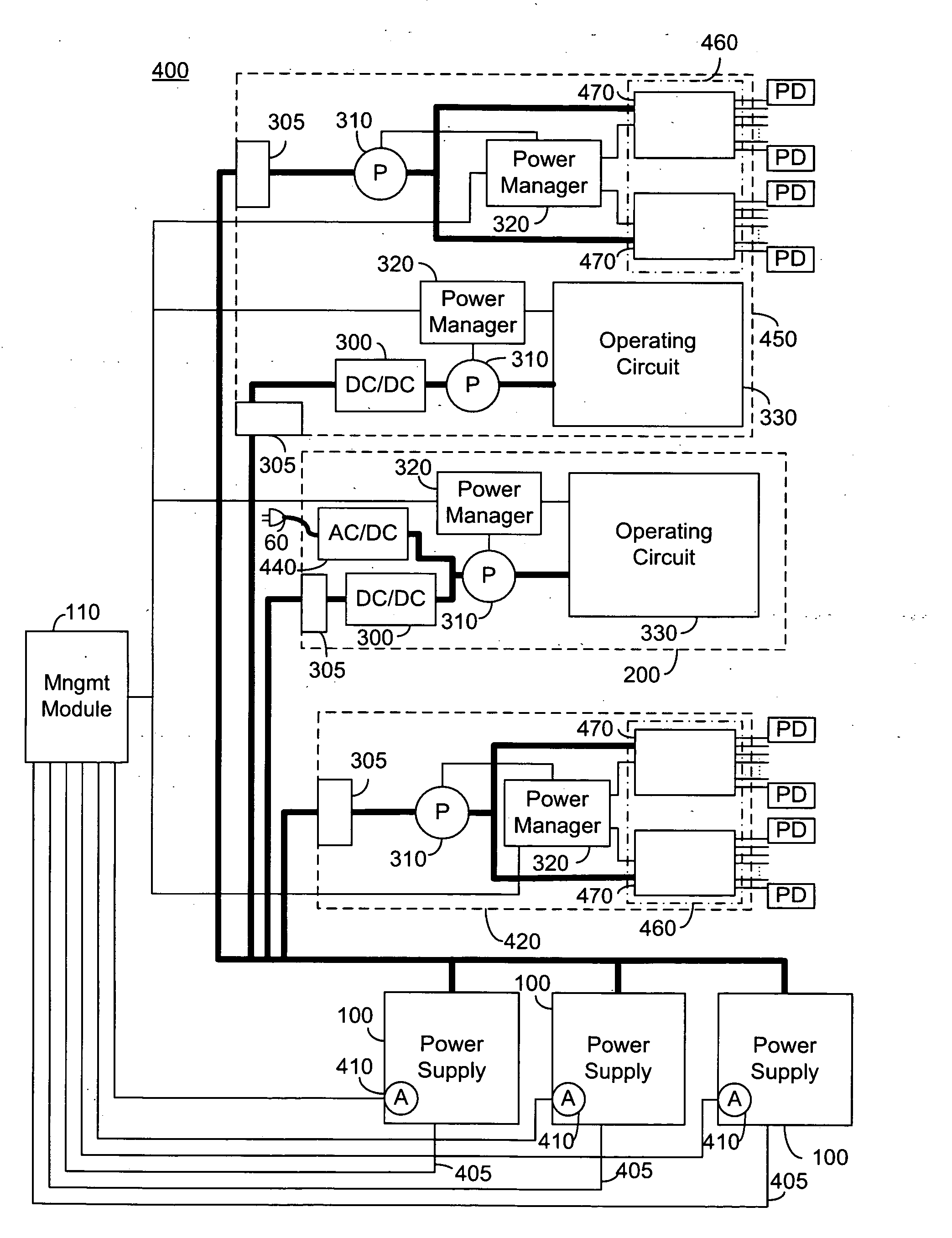
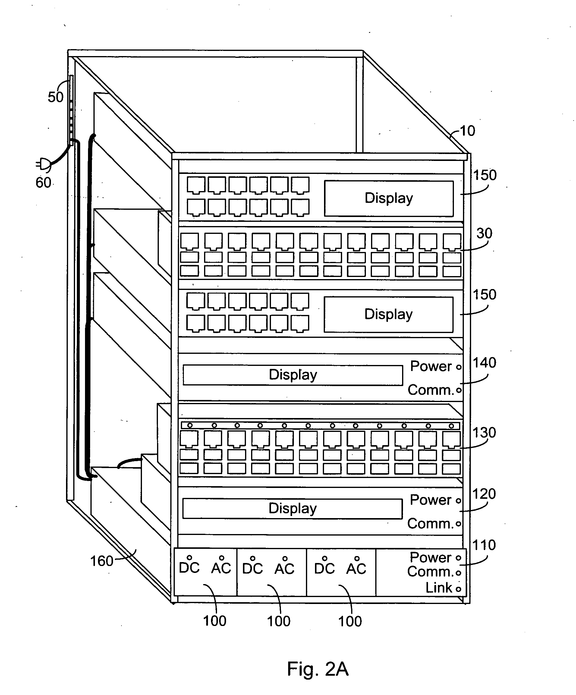
[0059]FIG. 2A illustrates a high level view of rack mounted telecommunication equipment according the principle of the current invention, comprising a rack 10 securing a plurality of power supplies 100, a management module 110, a power sourcing device 120, a power ready patch panel 130, a power managed module 140, a plurality of switches 150, a patch panel 30, a power strip 50 and a connection to AC mains 60. The plurality of power supplies 100 are shown contained within a single shelf 160 of rack 10 as a single power source, shelf 160 further comprising management module 110. Power managed module 140 may comprise a switch, hub equipment, modem, midspan PSE, computing equipment or gateway without exceeding the scope of the invention.

[0060] In an exemplary embodiment, shelf 160 is no more than 1 U high, and is designed with a backplane such that each of the plurality of power supplies 100 may be hot swappable. The backplane is further designed such that a power supply 100 may not be ...

second embodiment

[0063]FIG. 2B illustrates a high level view of rack mounted telecommunication equipment according the principle of the current invention comprising a rack 10 securing a first power shelf 210 comprising a plurality of power supplies 100 and a management module 110; a second power shelf 220 comprising a plurality of power supplies 100 and a redundant management module 110; a power sourcing device 120; a power ready patch panel 130; a power managed module 140; a switch 150; a switch having an on board power supply 200; a patch panel 30; a power strip 50; and a connection to AC mains 60. Power managed module 140 may comprise a switch, hub equipment, modem, midspan PSE, computing equipment or gateway without exceeding the scope of the invention.

[0064] In an exemplary embodiment, each of first power shelf 210 and second power shelf 220 is no more than 1 U high, and is designed with a backplane such that each of the plurality of power supplies 100 may be hot swappable. Each of first power ...


PUM


Abstract

A system for rack level power management, the system comprising: at least one power source; a management module; and a plurality of power managed modules in communication with the management module and connected to draw power from the at least one power source, each of the plurality of power managed modules comprising a power manager and an operating circuit, the operating circuit being operable at a plurality of power drawing levels responsive to the power manager, the management module being operative to allocate a power budget to each of the plurality of power managed modules and communicate the allocated power budgets to the power managers, each of the power managers being operative to control the operating circuit of the power managed module to be operable at a power drawing level within the allocated budget.

Description

CROSS-REFERENCE TO RELATED APPLICATIONS [0001] This application claims priority from U.S. Provisional Patent Applications Ser. No. 60 / 644,002 filed Jan. 18, 2005 entitled “System for Providing Power over Ethernet through a Patch Panel” and Ser. No. 60 / 695,190 filed Jun. 30, 2005 entitled “Backplane Power Management” and is a continuation in part of U.S. patent application Ser. No. 10 / 750,856 filed Jan. 5, 2004 entitled “Direct Current Power Pooling” which is a continuation of PCT Patent Application PCT / IL03 / 00832 filed Oct. 14, 2003 which claims priority from U.S. Provisional Patent Application Ser. No. 60 / 418,599 filed Oct. 15, 2002. This application is also a continuation in part of U.S. patent application Ser. No. 11 / 118,420 filed May 2, 2005 entitled “Method for Rapid Port Power Reduction” which claims priority from U.S. Provisional Patent Application Ser. No. 60 / 569,235 filed May 10, 2004. This application is related to co-filed U.S. patent application entitled “Rack Level Powe...

Claims


Application Information

Patent Timeline
IPC IPC(8): H02J3/14
CPCH02J1/102H02J1/14H02J9/061G06F1/26G06F1/3203G06F1/3287G06F1/3296H02H9/001H02J1/001H04L12/10H05K7/1457H05K7/1492Y02D10/00
Inventor PINCU, DAVIDBLAUT, RONIFERENTZ, ALONKORCHARZ, DRORGIAT, YANIV
Owner NEVERMORE SOLUTIONS
Why Eureka
Try Eureka