Magnetoresistive element

Inactive Publication Date: 2006-04-20
KK TOSHIBA
View PDF17 Cites 18 Cited by
  • Summary
  • Abstract
  • Description
  • Claims
  • Application Information

AI Technical Summary

Benefits of technology

[0043] A magnetoresistive element according to an aspect of the present invention includes a stacked structure comprised first and second ferromagnetic layers and a nonmagnetic layer

Problems solved by technology

Considering high integration of the magnetoresistive element having the ferromagnetic tunnel junction, a cell size must be reduced, and thus, the size of the ferromagnetic layer of the magnetoresistive element becomes inevitably small.
In addition, when switching (magnetization inversion) of a magnetization pattern of the ferromagnetic layer is carried out, a change of the magnetic structure becomes complicated.
This not only causes occurrence of noise, but also makes a coercive force large, so that a switching magnetic field increases.
Therefore, when the size of the ferromagnetic layer becomes small due to downsizing of the magnetoresistive element, there is a need for a large write current at the time of writing data, which brings an unfavorable result such as increased power consumption or shorter service life of wiring.
However, in the case where no inter-layered junction is present between the two ferromagnetic layers and only a static magnetic junction exists, the magnetic structure of the ferromagnetic layers becomes unstable.
In this case, a rectangular shaped ratio in a hysteresis curve or magnetic resistive curve becomes small, and it becomes difficult to obtain a large magnetic resistive ratio.
In addition, since there is a need for addition of the hard bias structure for fixing the edge domain, this structure is not suitable to higher density required for a large capacity memory or the like.
In this case, however, the size of the magnetoresistive element substantially increases, and therefore, this structure is not suitable to high integration required for a large capacity memory or the like.
However, in any case, the existing MTJ element having a broad bean shape or a cross shape cannot attain a write characteristic which can fully satisfy the requirements.

Method used


Image

  • Magnetoresistive element
  • Magnetoresistive element
  • Magnetoresistive element

Examples


first embodiment

(2) First Embodiment

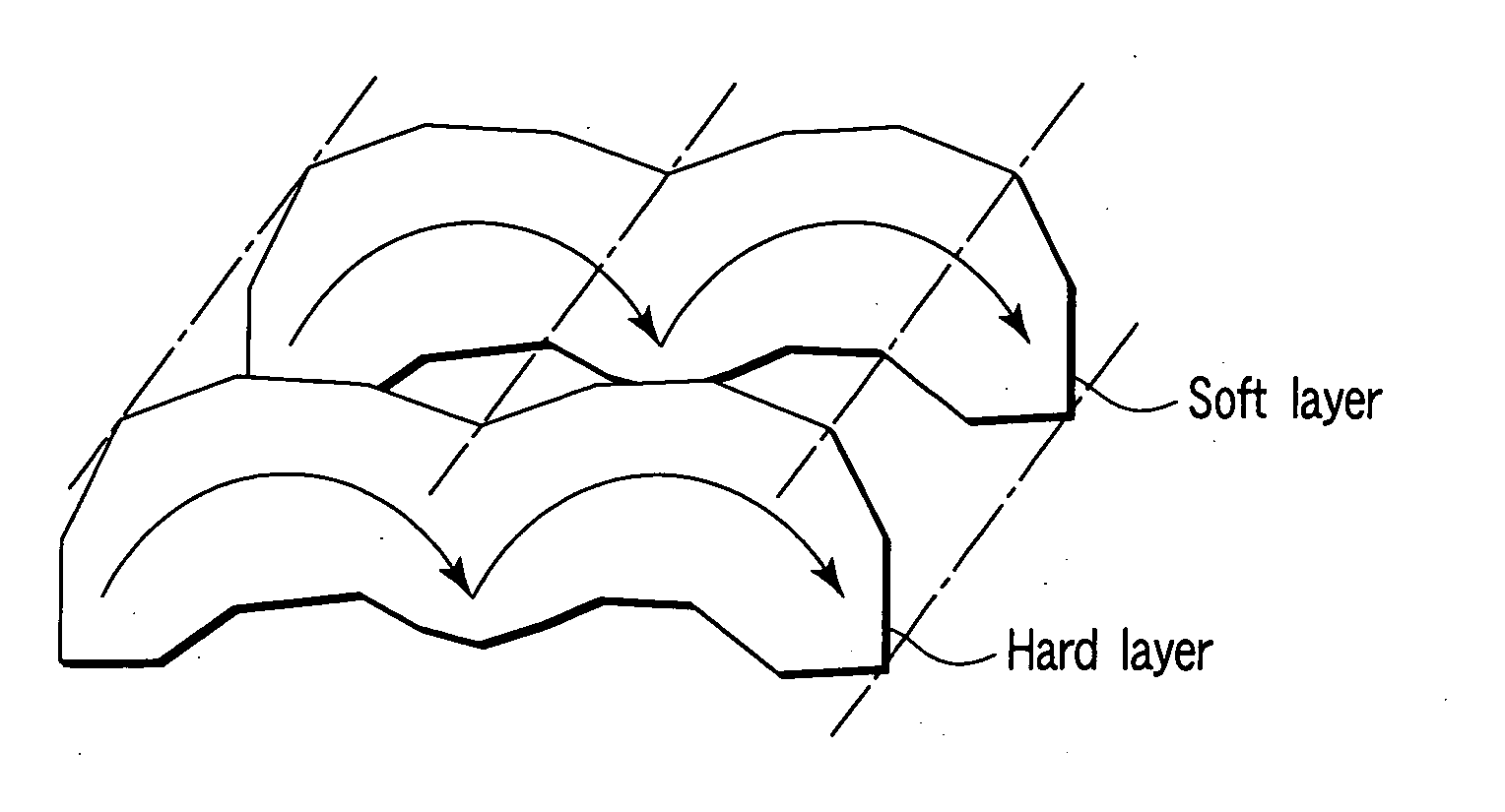
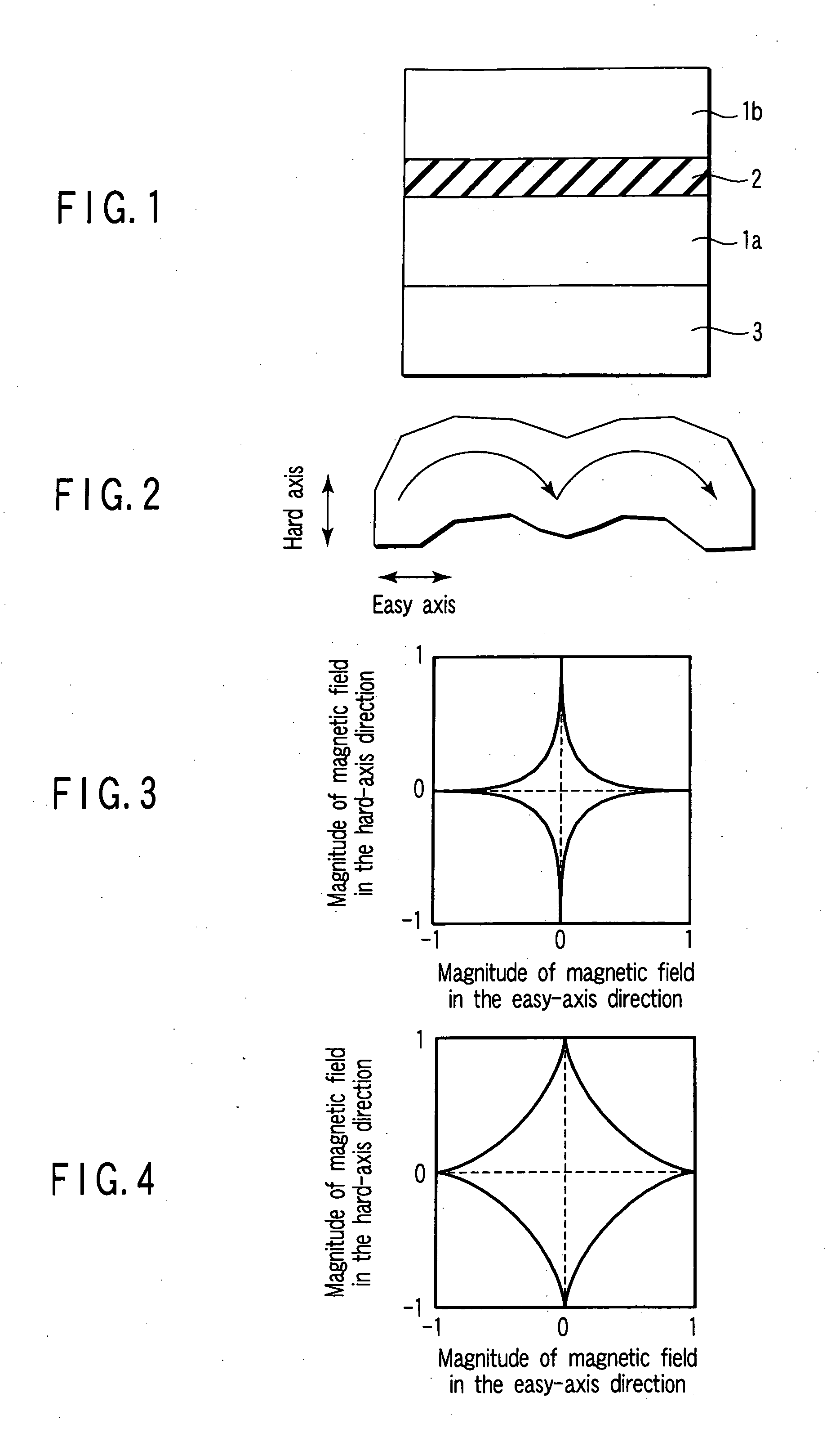
[0134]FIG. 2 shows a planer shape of a free layer of a magnetoresistive element according to a first embodiment of the present invention.

[0135] In this embodiment, the free layer of the magnetoresistive element has a planar shape formed by combining two characters C with each other. Specifically, the two characters C are disposed to be oriented in the same direction, to be oriented on a curved face in the hard axis direction, and to be adjacent to each other in the easy axis direction. The two characters C each have a planer shape approximate to character E or character M as a whole.

[0136] In this case, the residual magnetization of the free layer of the magnetoresistive element and the magnetization pattern in a region in which the magnetic field in the hard axis direction is zero or small each are comprised two C shape magnetic zones.

[0137]FIG. 3 shows a switching curve of the magnetoresistive element having the planar shape of FIG. 2. FIG. 4 shows a switchi...

second embodiment

(3) Second Embodiment

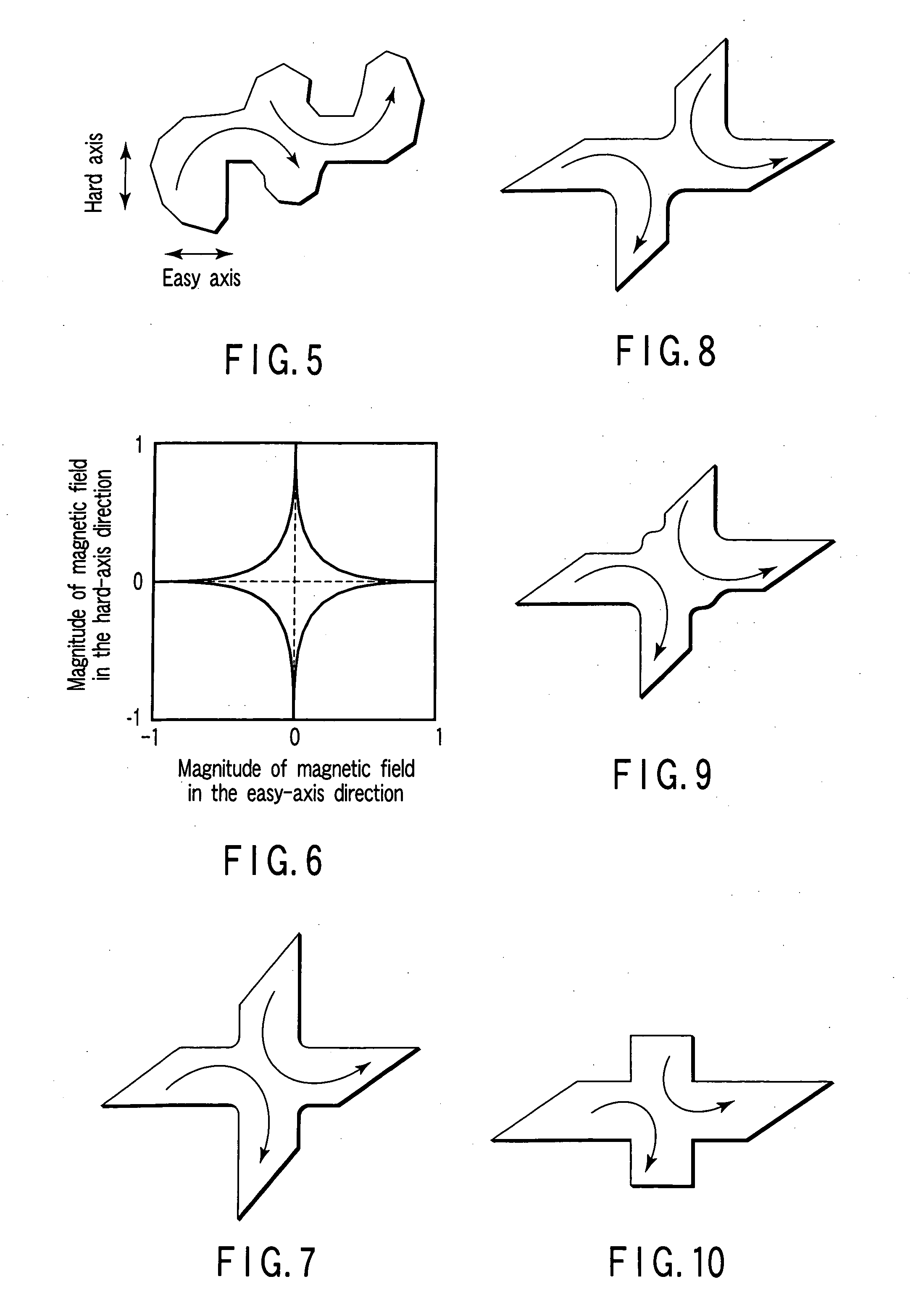
[0143]FIG. 5 shows a planar shape of a free layer of a magnetoresistive element according to a second embodiment of the present invention.

[0144] In this embodiment, as in the first embodiment, the free layer of the magnetoresistive element has a planar shape formed by combining two characters C with each other. However, the two characters C are oriented in different directions from each other, unlike the first embodiment. Specifically, the two characters C are combined with each other at their back, and are oriented in opposite directions to each other. Further, a curve face of the character C is comprised a shape such that the curved face is oriented in the hard axis direction, and is slightly shifted in the easy axis direction. The two characters C each have a planar shape approximate to character Z as a whole.

[0145] In this case as well, the residual magnetization of the free layer of the magnetoresistive element and a magnetization pattern in a region in w...

third embodiment

(4) Third Embodiment

[0151]FIG. 7 shows a planar shape of a free layer of a magnetoresistive element according to a third embodiment of the present invention.

[0152] In this embodiment as well, the free layer of the magnetoresistive element has a planar shape formed by combining two characters C with each other. The two characters C are oriented in different directions from each other, are combined with each other at their back, and are oriented in opposite directions to each other. In other words, the free layer of the embodiment has a shape such that two parallelograms are crossed each other.

[0153] Since the free layer has the shape such that the two parallelograms are crossed each other, the shape of a distal end of the free layer is comprised a tapered shape which is obliquely cut off instead of a rectangle.

[0154] An angle of the distal end (acute angle portion) of the free layer is set to be a value in a range of 20° or more and less than 90°.

[0155] The angle of the distal en...


PUM


Abstract

A magnetoresistive element according to an example of the present invention has a stacked structure comprised first and second ferromagnetic layers and a nonmagnetic layer disposed between these ferromagnetic layers, and a planar shape of at least one of the first and second ferromagnetic layers has a shape formed by combining two or more parts each having a shape of a character C.

Description

CROSS-REFERENCE TO RELATED APPLICATIONS [0001] This application is based upon and claims the benefit of priority from prior Japanese Patent Applications No. 2004-296457, filed Oct. 8, 2004; and No. 2004-314359, filed Oct. 28, 2004, the entire contents of both of which are incorporated herein by reference. BACKGROUND OF THE INVENTION [0002] 1. Field of the Invention [0003] The present invention relates to a shape of a magnetoresistive element, and is used for, in particular, a magnetic random access memory. [0004] 2. Description of the Related Art [0005] In recent years, with development of a magnetic memory element indicating a giant magneto resistive (GMR) effect, an element having a ferromagnetic tunnel junction has been used as a memory element of a magnetic memory. [0006] The ferromagnetic tunnel junction is comprised a stacked structure made of a ferromagnetic layer, an insulating layer, and a ferromagnetic layer, and a tunnel current flows in the insulating layer by applying a...

Claims


Application Information

Patent Timeline
IPC IPC(8): G11B5/33G11B5/127
CPCG11C11/15
Inventor KISHI, TATSUYANAKAYAMA, MASAHIKOFUKUZUMI, YOSHIAKIKAI, TADASHI
Owner KK TOSHIBA
Why Eureka
Try Eureka